Testing
FTTH
New network architectures (PONs or passive optical
networks) have been developed that allow sharing expensive
components for FTTH. A passive splitter that takes one
input and broadcasts it to as many as 32 users cuts the
cost of the links substantially by sharing, for example,
one expensive laser with up to 32 homes and only requiring
an inexpensive laser at each home. However, this
architecture changes the methodology of testing the
complete installed cable plant and links for proper
operation. Of course, individual links are tested as
usual, it is the PON coupler that creates the difference.
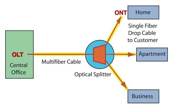
Each subscriber needs to be connected to the local central
office with a single singlemode fiber, through a
local PON splitter (or maybe two if the PON splitters are
cascaded.) Every home will have a singlemode fiber link
pulled or strung aerially to the phone company cables
running down the street and a network interface device
containing fiber optic transmitters and receivers will be
installed on the outside of the house. The incoming cable
needs to be terminated at the house, tested, connected to
the interface and the service tested. See FTTH
Architectures
for more information on typical FTTH installations.
FTTx
Testing Issues
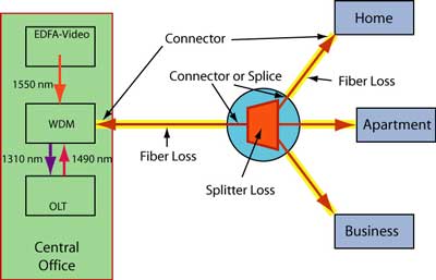
Testing FTTH network is similar to other OSP testing but
the splitter and WDM add complexity. FTTP PON networks can
be more complicated than simple OSP links, with WDM
couplers, PON splitters, etc. in a single link, so
complete testing can include some components and
installation issues not familiar to the usual OSP tech.
PON couplers add high loss, WDM couplers have different
performance at different wavelengths and connector
reflectance, not a problem in most systems, can be a
problem in short links typical in FTTx. Many FTTx systems
use APC (angled PC) connectors to reduce reflectance so
test cables for both OLTS and OTDR need to have matching
connectors.
However, once installed, users on
a live network means testing cannot disrupt service. Thus
testing may be as simple as checking power at the ONT on
the subscriber’s house with a calibrated fiber optic power
meter or just seeing if the ONT has a “green” connection
light!
The ONT at the home usually has some intelligence that can
be accessed from a remote location, allowing a service
tech to initiate a loopback test to verify connections at
any user. If only one user has a problem, a service tech
is then sent there, while if all users are down, the tech
is sent to the central office.
As with most fiber optic links, troubleshooting requires
knowing the architecture of the system, expected link
losses and optical signal levels and typical problems that
may be encountered. As always, we emphasize the importance
of having documentation on the system before testing and
troubleshooting.
Link
Testing
A link is a single run of fiber, e.g.: from CO to FDH or
from FDH to ONT. The fiber run may have connectors or not,
depending on whether the links are spliced or use
connectors for terminations. Quite a few now use
preterminated cables to speed installation. The loss of
the PON splitter must be included in the loss
budget
for the link.
See FTTH
Architectures
for more information on PON splitter losses. If you
need to test just the splitter itself, here
are directions.
You must measure loss with OLTS at all
wavelengths and bidirectionally to check all operational
modes - similar to how the transmission equipment will use
the fiber.
The installer may need to characterize each fiber with an
OTDR, verifying fiber attenuation, termination losses and
reflectance and splice quality. The OTDR will also show
any bending losses caused during installation. OTDR traces
should be filed for future reference.
Optionally, the installer may test splitters at the FDH or
the WDMs at the CO. If these are pretested, as they should
have been, this may not be necessary or advisable,
especially since it is time-consuming and costly. WDMs
also require specialized test equipment.
After the link is installed, it needs testing from end to
end. The end-to-end loss includes the connectors on each
end, the loss of the fiber in each link, the connectors or
splices on the splitter and the loss of the splitter
itself. Since the fibers are being used bi-directionally
and connector or splice loss may be different in each
direction if the fiber core diameter (mode field diameter
for SM fiber) is different, testing in both directions is
important too. Special FTTx PON OLTS are available that
test the proper wavelengths in each direction, simplifying
testing logistics.
Since PON links are generally short (<20km) chromatic
dispersion (CD) and polarization mode dispersion (PMD) are
not concerns. CD and PMD are generally only issues on very
long links.
BPON
Let’s consider the most complex version of PON testing,
BPON. It’s similar to OSP testing but splitter and WDM add
complexity as well as more loss and there are three
wavelengths in use. Tests include each coupler, each link
and end-to-end loss. Loss and reflectance are especially
important if systems are using an AM video transmission
system at 1550 nm, as it has a maximum tolerable loss and
reflectance before signals are noticeably affected. Tests
need to be done at all three wavelengths of operation:
1310 nm for upstream digital data, 1490 for downstream
digital data and 1550 nm for AM video downstream (BPON).
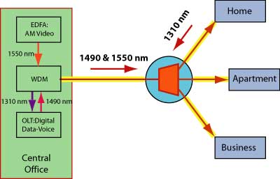
Insertion loss of the cable plant including the loss of
the coupler is tested using an optical loss test set
(special test sets for FTTH PONs are available that cover
all 3 wavelengths of interest.) OTDRs can be used if
length is adequately long, to determine connection
reflectance, fiber attenuation and troubleshoot problems.
Many systems will take OTDR traces and store for
troubleshooting. The splitters can confuse the OTDR so one
generally reverses OTDR test, taking traces from the
subscriber upstream.
OTDR
Testing PONs
Using an OTDR to test every fiber in an OSP link is
traditional, as the OTDR provides a snapshot of the losses
in the fiber, locates loss events (connectors, splices and
bending losses from improper installation), aids
installation troubleshooting and provides a trace which
can be stored for later troubleshooting and restoration.
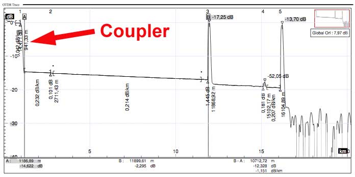
On FTTH PON networks, the PON splitter causes some unusual
traces on OTDRs, with the traces looking totally different
when tested from each direction. Here are two traces from
an actual system taken in two directions.
This trace is taken downstream from the CO to the
subscriber:
This trace is taken upstream from the subscriber toward
the CO.
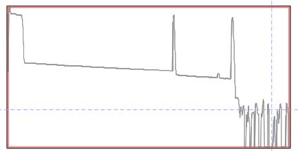
In both traces, you can see the large loss of the PON
coupler, best seen in the upstream trace at the bottom, on
the left side of the trace. On the downstream trace, it is
the large loss preceding the multiple peaks of the
subscriber fibers, marked with the dashed marker line.
Below we will show a simpler coupler and explain what you
are seeing here.
OTDR
Testing From
CO/Head End (OLT)
PON systems create problems for OTDRs. Shooting from the
input of a PON splitter at the CO, the OTDR sees and adds
together the backscatter traces from all the fibers. As a
result, it becomes impossible to see detail on individual
fibers, and an event (connector, splice of bending loss)
cannot be easily assigned to any individual fiber unless
the cable plant is carefully documented at installation.
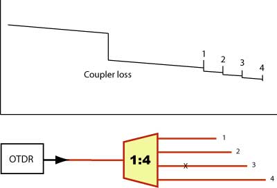
Consider the “X” shown in the splitter
diagram below. If it was a loss or reflective event, it
would show on the OTDR trace, but the operator would not
know if if were in fiber 1,2,3 or 4. The only unambiguous
part of the OTDR trace shown is the end of fiber 4, the
longest fiber, beyond the length of the next longest
fiber, #3.
It should be noted that FTTH links, because
of their short lengths and the use of some high power
transmitters, usually have APC connectors or fibers
prepared to have minimal reflectance. That can make
analyzing downstream OTDR traces very difficult when no
reflective end is available to mark the fiber end and
there are 32 fibers in the system.
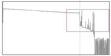
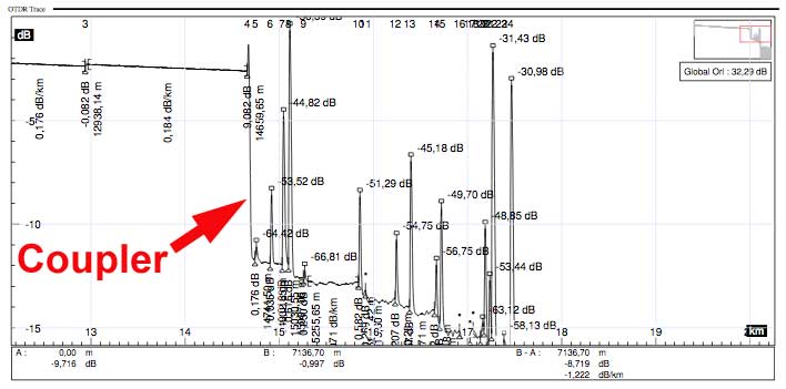
Here
is an illustration of how a real trace can become very
complex to analyze. This is an enlargement of the coupler
to subscriber section of the downstream trace above which
is outlined in red on the trace.
As a result of the complexity of
downstream traces, OTDRs are generally used on PONs from
the subscriber end toward the CO to characterize the fiber
path. However, the OTDR may also be used from the CO end,
because, as you can see from the diagram above, it allows
the operator to quickly characterize the length of each
fiber link, providing actual fiber length to add to
network diagrams for future troubleshooting.
Special PON OTDRs will test at 1310,
1490 and 1550 nm. Some also test “out of band”
at 1650 nm, which is more sensitive to bending losses and
allows in-service testing with a filter to remove signal
wavelengths. Since PONs are short, the OTDR needs very
high resolution, usually obtained by having the shortest
test pulse that will give adequate range.
Testing PONs in the downstream direction is helped with
launch and receive cables. The launch cable allows testing
the initial connector on the link as well as allowing the
initial overload of the OTDR to settle down as with any
OTDR test. But on the receive end, if a cable of known
length is used, say 100m or 500m, one can look back
exactly that distance from the reflective end to see the
loss of the end connector.
OTDR
Testing From Subscriber
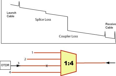
Testing from the subscriber end is easier. The fiber path
will show events on just one fiber, like the “X” shown on
fiber 3, and a high loss for the coupler. Here a 1:4
coupler will have 6 dB of splitting loss plus
perhaps 1dB excess loss for a total of 7 dB loss.
Using
launch and receive cables allow testing connectors on both
ends and measuring end to end loss.
Here is a detailed trace from the upstream example above,
showing how much simpler the trace is when the other
subscriber links are not shown.
Issues With OTDR Testing PONs
If you are testing a GPON network, the working loss range at the subscriber should be
~13 to 28 dB for a 32 split. There are other versions
with more dynamic range too. If you are doing a FTTH loss budget, a total split of 32 should be ~ 18 dB for splitters plus all fiber, splice and connector losses.
Testing with an OTDR should be done upstream from individual subscribers
and the OTDR needs to be expecting ~ 18 dB plus fiber to as much as the
28 dB loss limit, so that’s equivalent to nearly 50km of just fiber.
You will need a fairly long test pulse to get that dynamic range or a
lot of averages. With that long a pulse, you are going to have
resolution problems on typical short FTTH PON networks.
Testing PONs requires an OTDR with what seem like conflicting specs -
high dynamic range and high resolution. Most OTDR manufacturers offer
specific instruments for this application.
The problems with testing a PON network, especially a cascaded one, with
an OTDR is the losses at the splitter create conundrum for OTDR setup -
if you set up the OTDR for range, generally increasing the pulse width
as you would for a long cable with high loss, you lose the resolution
you need for the short PON network. A better alternative is increasing
the number of averages, which adds time for testing.
Perhaps a better solution is to use a design that adds test points with
connectors around all the splitters to allow testing the link segments
between splitters individually.
Other
FTTx Testing Issues
Network equipment will be tested as the system
is turned on or for troubleshooting. Will the network
equipment transmit and receive properly? If the cable
plant is installed correctly and tests within
specifications for loss and reflectance, it should. Most
FTTx equipment has extensive self-testing capability and
that may prove sufficient for most testing. PON couplers
may have a second port on the upstream side just for
testing or unused downstream connectors may be useful for
testing, especially with OTDRs. And the subscriber side of
a splitter usually has several unused ports for future
expansion that can be used for testing.
The network equipment should be tested for optical
power. The transmitter output should be within
specifications, as should the receiver input, when tested
with a
calibrated
optical power meter set at the proper wavelength(s). If
testing is done while all three systems are operating at
their respective wavelengths, a power meter with
wavelength selective input is required. Power at the
receiver is critical. Too low and the signal-to-noise
ratio will be too low; too high and the receiver will
saturate. Both conditions will cause transmission errors.
High power is not uncommon, so attenuators may be used in
these links to reduce power to acceptable levels.
Data transfer testing with a protocol analyzer is the
final test. It will be done using specific protocol
testers for the data formats being transmitted. Personnel
doing these tests are probably not the same that test the
cable plant as each have specific training and test
equipment needs.
ONTs
are generally capable of loopback testing under remote
control. This may mean more sophisticated testing is
unnecessary for troubleshooting.
FTTx
Safety Issues
FTTx safety issues include all the usual fiber
installation issues, for example working with bare fibers,
solvents and adhesives. But FTTx networks have several
other potential problems.
BPON links carrying AM CATV signals will have high power
from EDFAs, especially before the splitters. And links may
have multiple equipment transmitting simultaneously.
Either case can cause high optical power that can be
dangerous to worker’s eyes. Care should be taken to not
expose eyes to light from the fibers and to always use
microscopes with infrared filters, just in case. Since
systems may have multiple systems transmitting on the same
fiber, it is harder to ensure that all systems are turned
off for inspection or testing, also.
And, since up to 32 users may be sharing the CO based
network equipment, turning off systems for troubleshooting
is not desirable, so testing may have to be done with
equipment in service. Exercise care. More
on fiber optic safety.
- Technical
Information on FTTX From The FOA
Online Guide:
- FTTH
Introduction
- FTTH
Architectures,
- FTTH
in MDUs (Multiple Dwelling Units)
- FTTH
PON Standards, Specifications and Protocols
- FTTH
Design
- FTTH
Installation
- FTTH
Customer Premises Installation
FTTH
Network Testing
FTTH
Case Studies: Do-It-Yourself FTTH
FTTH
Project Management
Migration from GPON to 10GPON
The
Fiber Optic Association Fiber To The Home Handbook: For
Planners, Managers, Designers, Installers And Operators Of
FTTH - Fiber To The Home - Networks
The
Fiber Optic Association Fiber To The Home Handbook
Available
in paperback or as an eBook on the Amazon Kindle Available
direct from Amazon.com,
local booksellers and other distributors.
- Training
& Certification
Fiber
U Online FTTx Self Study Program (free)
- FOA
Certification Overview
FOA
FTTx Certification Requirements
FOA-Approved
Training Programs
Table of Contents: The
FOA Reference Guide To Fiber Optics
|
