Fiber To The Home
Network Design
There is really no way to generalize on the design process
for fiber to the home (FTTH) networks - or any fiber optic
network for that matter - since every system is unique. If
you are familiar with FOA's other design materials, you
know we don't give you formulas or outlines to follow.
Rather than telling you how to design a FTTH network, we
will illustrate some of the different network
architectures, construction methods, etc. possible, then
offer options that may work for your network and stimulate
your design processes.
If you are new to fiber optic network
design, we recommend you study the
design pages on the FOA Guide, read the FOA textbook
Reference
Guide to Fiber Optic Network Design, and
perhaps take the
Fiber Optic Network Design self-study course on
Fiber U to prepare yourself for designing your own
network. That will help you understand how to design and
install systems most efficiently before beginning your own
project. And, of course this
complete series on FTTH here on the FOA Guide.
The best way to understand the options
in FTTH network design is to consider several very
different types of networks which differ by subscriber
density, geography and technical issues which affect the
design decisions that must be made.
- Urban
- Suburban
- Multi-dwelling
Units
- Rural
Within each of these we will discuss design options that
have been proven successful in the real world. We will
look at how to design the architecture of the system as
well as the design of the cable plant itself, down to the
component level. We will also look at cost implications
and future upgrades. We'll try to illustrate the options
to help you understand them.
We begin with some important background material.
Jargon
PON (Passive
Optical Network)
Most FTTH networks are based on passive optical
network architectures, simply because that's usually the
lowest cost way to design a FTTH network. There are other
architectures that may be preferable in some circumstances
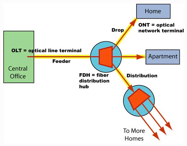
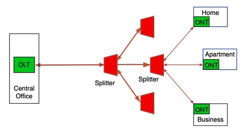
and we'll discuss those too. This drawing shows the
location of the hardware used in creating a typical PON
network. This drawing also defines the network jargon for
cables: a "feeder" cable extends from the OLT (optical
line terminal) in the CO (central office) to a FDH (fiber
distribution hub) where the PON (passive optical network)
splitter is housed. It then connects to "distribution"
cables that go out toward the subscriber location where
"drop" cables will be used to connect the final link to
the ONT (optical network terminal).
Active Star
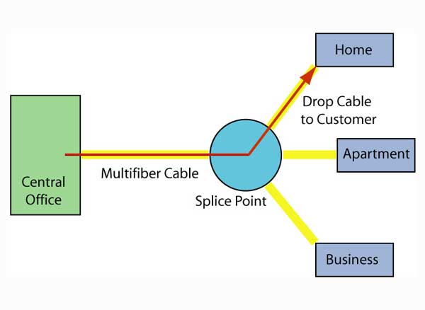
An alternate to
a PON is an active star network, also called a
point-to-point (P2P) or "home run" system where each
subscriber has a dedicated fiber and Ethernet link to the
head end or central office. The main difference with
a PON is the amount of fiber required for the network,
especially if the service provider's switches are located
at the head end. Switches can be remote, closer to the
subscribers, but the switch requires power, a UPS and
perhaps even heat/AC, making that option much more
complex.
We will focus on PONs but mention
P2P and even some options for wireless or wireline for
drops.
Gig or 10Gig?
Standards for PONs give you an option
of gigabit or 10 gigabit networks. Technically what is
called gigabit (G for short) is regular GPON which offers
OLT ports at 2.5G downstream and 1.25G upstream, shared
among 32 (normal) or 64 (rare) users. Provisioning is
generally for 1G down and some lower value up on each OLT
port. If you don't understand the stochastic nature of
networks, you might assume that 32 users with 1Gb/s of
bandwidth have only about 30Mb/s (1Gb/s = 1000Mb/s, divide
by 32 = 31.25Mb/s). But that's not realistic. The full 1G
of bandwidth is available to all users who only use it a
fraction of the time, so their data is transferred at 1G
speeds. Average usage for most FTTH networks averages only
a few Mb/s, so 1G PONs are very effective.
But 10G PONs are available and like all
electronics, costs keep coming down, so they are being
considered for many networks. It is doubtful that any FTTH
network aimed
at consumer subscribers needs 10G, but some business
customers might. The GPON designers were clever, however,
making 10G use different wavelengths than 1G, so if you
build a 1G GPON network, you can upgrade at any time - say
to accommodate a network expansion aimed at businesses -
and run both networks simultaneously over the same cable
plant. Generally, we recommend building networks at 1G to
take advantage of the lower cost electronics, but knowing
that upgrades can be made simply and use the very same
cable plant.
Network
Architectures
PONs have options on architectures that can affect cost
and ease installation. One of the first decisions the
designer needs to make is where to locate splitters as
that will affect other hardware decisions like how many
fibers should cables have and what types of hardware to
use. To make that decision, one first needs to understand
the distribution of subscribers as location and density
are important for designing an efficient system. Here are
some options on design:
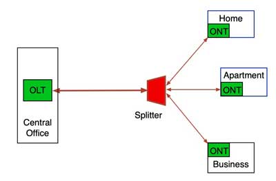
PONs work on the principle that
splitters allow one central port to communicate with 32 or
64 users over a single fiber to the splitter and then a
single fiber to each user. Typical PON architectures are
shown like this:
In reality, there is a lot of
flexibility in the location of splitters. For example,
some dense urban or suburban networks move the splitter
into the Central Office (CO - a traditional telecom term)
or Head End (the CATV term) and run a fiber to every user
like this:
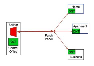
While this option requires more fiber,
large fiber count cables are readily available and fiber
cost is low, so the incremental cost to use more fibers in
a cable is reasonable. If the splitter is in the CO, the
OLT can be utilized more efficiently since each port can
support 32 or 64 users from any location in the service
area. If splitters are moved closer to the users, some
ports must be left open for future expansion, meaning that
OLT port will support fewer than the maximum number of
users - about 24 ports being used seems average, with 8
ports being open for future subscribers. With a central
splitter and fiber to each user configuration, there is
flexibility to use each OLT port more efficiently, adding
new OLT ports only when needed, and when every customer
has a dedicated fiber, the CO can even support several
ISPs (Internet Service Providers) by simply patching the
user to their chosen ISP.
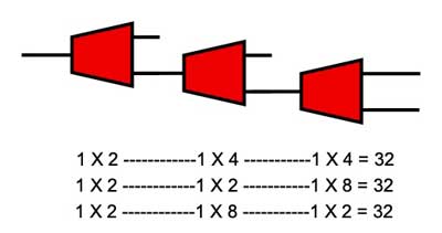
Where subscriber density is lower, it's
common to cascade splitters where splitters with fewer
splits are connected to other splitters in series like
this:
Cascaded splitters are useful for areas
like the suburbs or rural areas where subscribers are
spread out but often in clusters. An example is to use a 4
or 8 port splitter to serve a street in the suburbs or a
small cluster of homes in a rural area or to connect
multiple users in a multi-dwelling unit (apartment or
condo building - see the section on MDUs below.)
PONs are standardized on splits of 32
or 64 per OLT port, and the economics of the electronics
depends on the efficient use of the OLT port. But
subscriber take rates are not 100%, so one needs to leave
spare ports for drops to future subscribers. Some systems
limit subscribers to 20-24 per port to allow new
subscribers. Others have built networks around a fiber
from the head end to every potential user and leaving the
fibers to non subscribers dark. The central office houses
all the splitters which can be fully populated, optimizing
the electronic ports. New subscribers already have a dark
fiber and just need plugging into a splitter at the head
end. New OLT ports are added as subscribers fill up ports
already in use.
Much of the design time is likely to be
spent deciding where to place splitters to optimize the
cable plant. In dense urban areas, there may be locations
where subscriber density is high enough to justify using a
single 32 port splitter. In less dense areas, it will
probably be more efficient to cascade splitters to equal
the 32 splits. Splitters come in binary ratios (2, 4, 8,
16, 32) and can be cascaded in any sequence as log as the
multiplied split ratios are no more than 32, e.g. 2+16,
4+8, 2+4+4, etc.
Choosing splitter locations can be
challenging, but generally it is done where one finds
groups of subscribers in close proximity so the length of
drop cables is shortest. In urban or suburban areas, one
can look at the number of residents in a building or the
number of homes on a street. In dense population areas, a
pedestal or underground fiber distribution hub (FDH)
containing splitters may be placed in a neighborhood and
drops run from the FDH to buildings from there. If a
building has many residents, a smaller FDU with splitters
may be placed inside the building with individual fibers
run to each subscriber. A large FDH is not needed for
splitters. Splice closures often have provision for
splitters, so a backbone or distribution cable can be
split out to drop cables for subscribers in the closure.
That closure can be in a manhole or handhole if the cable
plant is underground or suspended with aerial cable.
PON Loss Budgets
PONs are designed around a certain
split ratio for OLTs and have a range of power at the
receiver that must be met for the network to function. For
example, GPON has a Power Budget range of 13dB
(min) to 28dB (max) w/32 split. When calculating the loss
budget, one needs to ensure the loss is at least 13 dB but
less than 28 dB, usually less the acceptable loss margin
for the link. The minimum of 13 dB is usually not going to
be a problem since splitters add large amounts of loss.
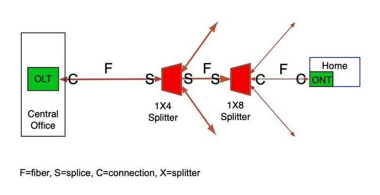
PON network diagram with loss budget components noted.
PON networks with splitters require
calculating a loss
budget like any other network. Besides the losses
from fiber length, splices and connections, one must add
in the loss of the splitters. Each split of a factor of 2
loses 3dB and in addition there are losses due to splitter
inefficiency, so losses can be quite high. In the example
above, the splitters are cascaded so one would have a 1X4
with 7 dB loss and a 1X8 with 11 dB loss to include in the
loss budget for a total splitter loss of 18 dB. The the
loss of the remaining components in the cable plant would
be added.
| Splitter
Ratio |
1:2 |
1:4 |
1:8 |
1:16 |
1:32 |
| Ideal
Loss / Port (dB) |
3 |
6 |
9 |
12 |
15 |
| Excess
Loss (dB, max) |
1 |
1 |
2 |
3 |
4 |
| Typical
Loss (dB) |
4 |
7 |
11 |
15 |
19 |
After calculating a loss budget, it
needs to be compared to the power budget of the PON
version or link (if using P2P architecture) chosen
for the network.
Rural Architecture Options
Rural areas are characterized by low
subscriber density and long distances, not the conditions
PONs were designed for. There is a "long reach" GPON
version with a capability of 64 users and 60km that can
work in some applications. Another option sometimes
considered is not using splitters but taps, special
splitters at drops that are not symmetrical - multiple
equal outputs - but split off a small portion of the
signal in the fiber, like 10% and pass 90% along to the
next drop.

The problem with the tap architecture
is the inefficiency of tap splitters, The excess loss in
taps can be as much as 1dB per tap. That excess loss adds
up fast, rapidly cutting the length the network can reach
(1dB = ~2.5km of fiber). FOA has done an analysis
of the use of taps in rural FTTH which can be used
as a model for analyzing the use of taps in any FTTH
network.
Another option which has been developed
for low subscriber density like rural areas uses is a
remote OLT with only a few ports. OLTs designed for CO use
generally have options for many OLT ports because they are
intended for applications with large numbers of users -
hundreds of thousands in a dense city. But rural areas may
only have a few subscribers in a small town or scattered
along country roads. Large numbers of ports are not
needed. What is needed is an architecture that allows a
service provider to connect users spread out over large
areas.

The remote OLT option allows creating a
"head end" periodically along a rural road where users are
grouped. The Remote OLTs can take advantage of the fibers
already installed along many roads and since some allow
"daisy-chaining," the use of two fibers along the route is
all that's needed. They are in small enclosures similar to
CATV amplifiers and can be mounted on poles or suspended
from messenger wires.
The
long reach version of GPON is another option for rural
areas. It can reach 60km with up to 64 users per port, but
in countries like the US, 60km is short compared to the
distances in rural areas. And it will use much more fiber
than the remote OLT architecture.
FTTH Fiber
Optic Cable Plant Design
When FTTH using PONs first began being installed around
2005-7, it was considered a extension of regular telephone
systems, where subscribers were being connected to a
telephone system replacing copper wires. Cabinets or
pedestals containing the PON couplers were placed near a
group of subscribers. Cables were pulled between the
cabinet and the central office containing the PON system
electronics and spliced on each end by the usual outside
plant (OSP) installation crews and were tested as was
normally done with telecom fiber optic networks.
On the subscriber end, drop cables were
placed to the home and connected either by splicing or
installing connectors (usually APC connectors to prevent
reflectance problems). Drop cables could be installed
aerially, underground or buried. Installing the cables
through customer's yards created a problem as it is time
consuming and disruptive to the customer. Simple trenching
was sometimes dropped in favor of directional boring, an
expensive process. Connectors were installed either by
fusion splicing on pigtails or using splice-on connectors.
After the cable plant was installed,
the optical network terminal (ONT) was installed at the
home. Some systems installed ONTs on the outside of the
house, some inside garages, some inside the home. Some
home builders built new homes with provision for the ONT
inside the home and installed cabling and power to the
same area to create a home prepared for broadband. See the
examples below.
After the ONT was installed and tested,
it was necessary to complete the installation by
connecting the customers phones, TVs and computers. In
all, three or four groups of installers of different
experience and skill levels were needed to install a FTTH
customer.
Systems Evolving With Experience
After some experience with the systems,
methods were tried to simplify the process and cut costs.
A big breakthrough came with the development of prefabricated
cabling systems (sometimes call pre-terminated
cabling) that eliminated the need for most of the
splicing. Cables with weatherproof connectors were
purchased already made to the lengths needed and pedestals
were factory made with connectors for the drop to the home
and a cable ready to splice onto the cable installed from
the central office.
The prefab drop cables could be run
aerially, even lashed to current telephone wires. They
were also small enough they could be pulled through small
PVC conduit often installed to home in new construction.
Most of the systems use multi-connector cables near the
homes being connected so homes can be connected during the
first install or later when more customers decide to take
the service.
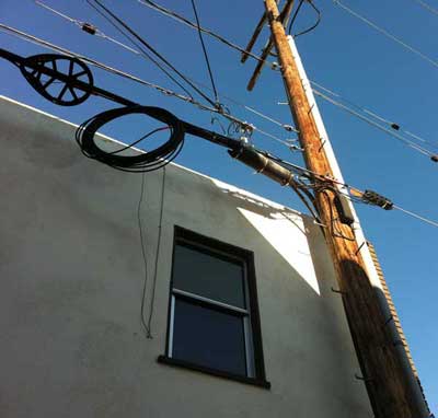
Aerial
installation in Santa Monica, CA, using prefab cabling
system.
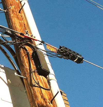
Closeup of the six-port drop.
If the cable is underground, it will usually be
pulled through conduit from connection to the distribution
cable or the splitter to the home. Here a preterminated
system has two home drops connected to the distribution
cable.
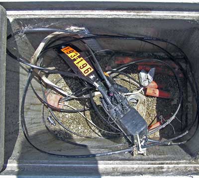
Underground installation of prefab cable system in Long
Beach, CA.
Other systems used microduct
installation which requires little or no digging to
install underground or under a road. Microducts are
designed to accommodate small microcables that are
installed by "blowing in" the cables, a technique used in
many systems.
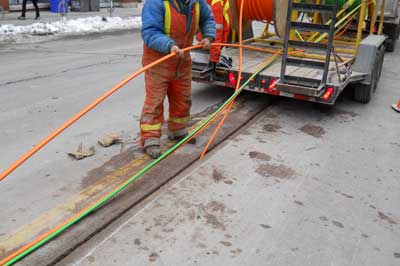
Microduct
installation using a saw on a paved street.
The splitter can be housed in a central office, a
pedestal or even a splice closure used for drops in the
neighborhood near the homes served. The advantage of PONs
is that the pedestal or splice closure is passive - it
does not require any power as would a switch or node for
fiber to the curb.
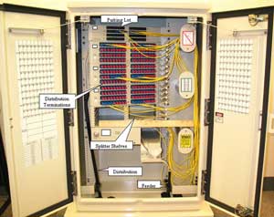
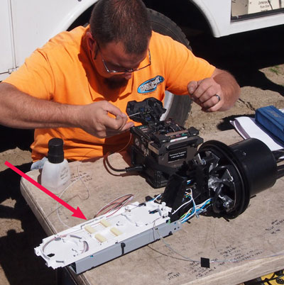
On the left is a typical pedestal that has connections to
the CO, splitters and fibers out to each home in a sealed
enclosure. Pedestals like this can be specified and
purchased ready to install; installation involves only
splicing the distribution cable to a short cable provided
as part of the pedestal. On the right, a tech is splicing
drop cables in a closure that has provision for a splitter
in the splice tray (red arrow.)
A network interface device called an ONT
(optical network terminal) containing a fiber optic
transceiver will be installed at the house. Some are
installed on the outside of the house, others are indoors.
Some houses are now being built with cabinets in the house
for connecting to the FTTH fiber and then distributing
phone, TV and Internet connections throughout the house
over state of the art cabling. The incoming cable needs to
be terminated at the house, tested, connected to the
interface and the service tested.
Basic Component Selections
Two components of FTTH cable plants are
almost universal. Every network should use standard
singlemode fiber, G.652, or its bend-insensitive
equivalent G.657, in all the cabling. This is regular SM
fiber and is appropriate for current PONs as well as
upgrades to 10G PONs in the future. Connectors are
generally SC-APC, the SC connector with an angled physical
contact ferrule to reduce reflectance problems in the
short cables and splitters. Check equipment requirements
to see if SC-APC connectors are specified or if SC-PC is
required for the transceivers. Beyond these basic choices,
cable designs and other hardware will be chosen for the
environment of the cable plant.
New Cable Types And Hardware For Subscriber Drops
Several new cable types were developed for use in
FTTH. Until FTTH, most single fiber cables were
complicated structures with tight buffered fibers and
aramid fiber strength members inside plastic jackets,
usually 3mm in diameter or sometimes smaller. While these
cables were adequate for factory termination into
prefabricated assemblies, they were not ideal for field
termination or use inside buildings. With the advent of
bend-insensitive fibers that required less protection, a
new type of drop cable was developed that molded a
bend-insensitive fiber inside a small plastic structure
surrounded by metal or aramid fiber strength members. This
design could also be made as a "figure 8" cable with a
messenger for support in aerial installation. Here are
some photos of this type of cable.
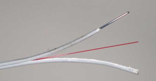
FTTH Drop Cable,
1 fiber, showing steel strength member
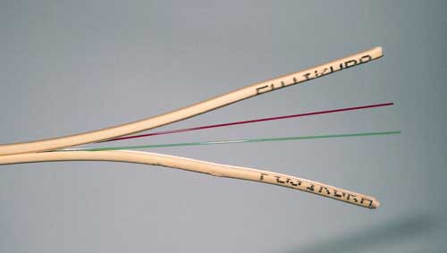
FTTH Drop Cable,
2 fiber
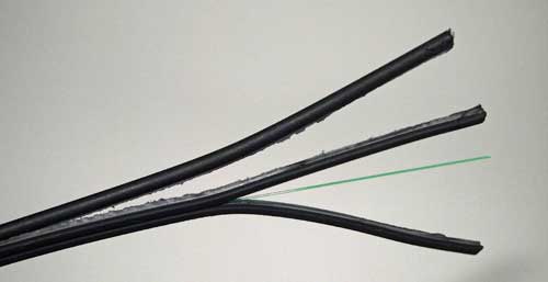
FTTH Drop Cable,
1 fiber with messenger for aerial support
To work with
these cables, special fiber closures were developed that
are more convenient for field installation.
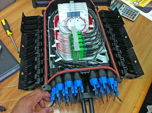
This
closure has entries for distribution cables, including one
coming in and one going out - continuing on to
another closure for daisy-chained cables using midspan
access. There are multiple outputs for drop cables which
are terminated in connectors. Some closures like this one
have provision for splicing on pigtails to terminate the
distribution cables while others are designed for direct
termination using prepolished-splice connectors. Patching
with connectors in a re-enterable closure allows adding
new drops when needed.
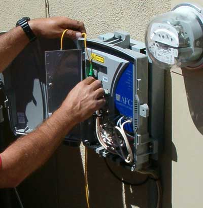
Early ONTs being installed on the
outside of the house looked like this. Most networks have
moved to just installing a demarcation box on the outside
of the house where the drop cable is connected to a fiber
optic cable running into the house. This connection allows
for a test point for techs where they do not have to enter
the house to see if signal is being received at the house.
Inside, the FTTH ONT is now a small box like a cable or
DSL modem.
A house with
premises cabling has this cabinet inside the home for
distributing services from the FTTH connection. Some
builders now include equipment boxes like this in new
homes.

Design For
Geography
The best way to understand the options in FTTH network
design is to consider several very different types of
networks which differ by subscriber density, geography and
technical issues which affect the design decisions that
must be made.
- Urban
- Suburban
- Multi-dwelling
Units
- Rural
Urban
FTTH Networks
Urban FTTH networks feature high
subscriber density requiring less fiber because the
distances are shorter and more splitters and head-end
electronics because the subscribers are more numerous.
In dense urban areas, many if not most users are going
to be in MDUs, so the OSP design and installation
can be simpler - just getting fiber to the building -
but inside the premises it may perhaps be more
complicated - how to run fiber inside the building to
each subscriber. See the section on MDUs below.
Inside a city, the most complicated
part of designing a network is accommodating the cables
needed to get from the CO/Head End to the building where
the users are located. Cities often have congested
conduits with too many cables already, so running more
cables can be a problem. Techniques exist to add cables
to crowded ducts, sometimes removing fiber ducts that
have only one fiber and replacing them with microducts
with multiple microcables or using fabric ducts that can
double or triple the number of cables a conduit can
accommodate. Rather than digging up streets, systems can
be built using microtrenching with minimal impact.
Techniques also exist to remove the core of CATV
hardline coax and use the jacket as a fiber duct and use
robots to install cables in sewers. Fiber optic
companies can be quite inventive.
Most cities have the majority of
cables underground, but many also have aerial cables in
alleys. If possible, running FTTH cables in alleys
behind buildings and using aerial drop closures will
greatly reduce the cost of building an urban FTTH
network.
But before deciding how to install
more cables, inventory what exists already. Many cities
have fiber optic cable plants installed for city
communications, security, traffic systems, citywide
WiFi, etc. and may have spare fibers. If no spare fibers
exist, it may be possible to use wavelength division
multiplexing to get more links. Likewise, other service
providers including electrical utilities may have fiber
or spare conduits that can be used, and their interest
may be higher if they can benefit from the new network.
Another problem in cities is finding
space for fiber hubs where drop cables connect to the
distribution cables. They can take up lots of space and
be a problem in cities where sidewalk space is at a
premium and underground utilities crowd the areas under
streets and sidewalks. Putting hubs inside buildings may
be much easier that doing major construction outdoors.
FTTH In
Multi-Dwelling Units (MDUs)
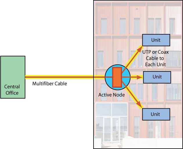
Multi-dwelling units (MDUs in some suppliers jargon) are
sometimes handled like FTTC, where fiber is brought into
the building and individual units are connected over
copper cables, either twisted pair from phones or computer
networks or coax from CATV or satellite. A standard for
Ethernet over CATV Coax (MOCA) is often used to make this
connection if the telephone wires are inadequate, but be
careful as those cables may not be owned by the building
owner but the service provider.
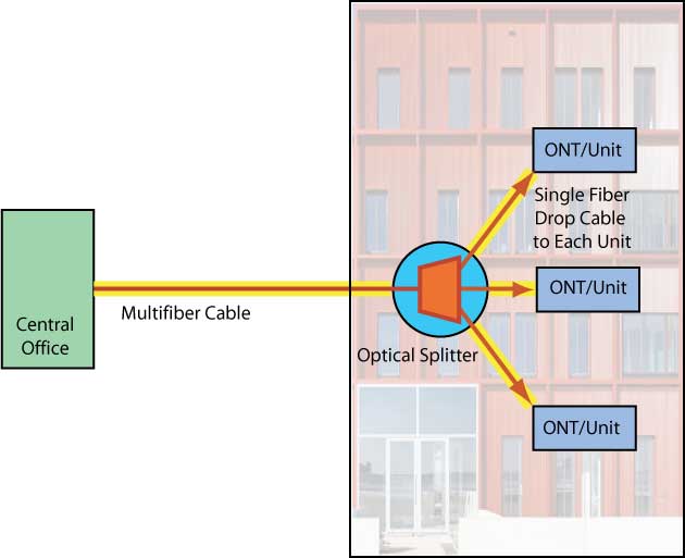
But MDUs are ideal
for FTTH (that is to each unit in the building) since
there are many users in a very small space and fiber
lengths are short. Besides using less fiber, MDUs
generally require less time per drop to install. One issue
is where to place PON splitters. If it is a small
building, the splitter(s) can be installed at the entry
facility and individual cables run to each unit. In larger
buildings, splitters can be cascaded and a splitter placed
on each floor (if space permits) and short cables run to
each unit.
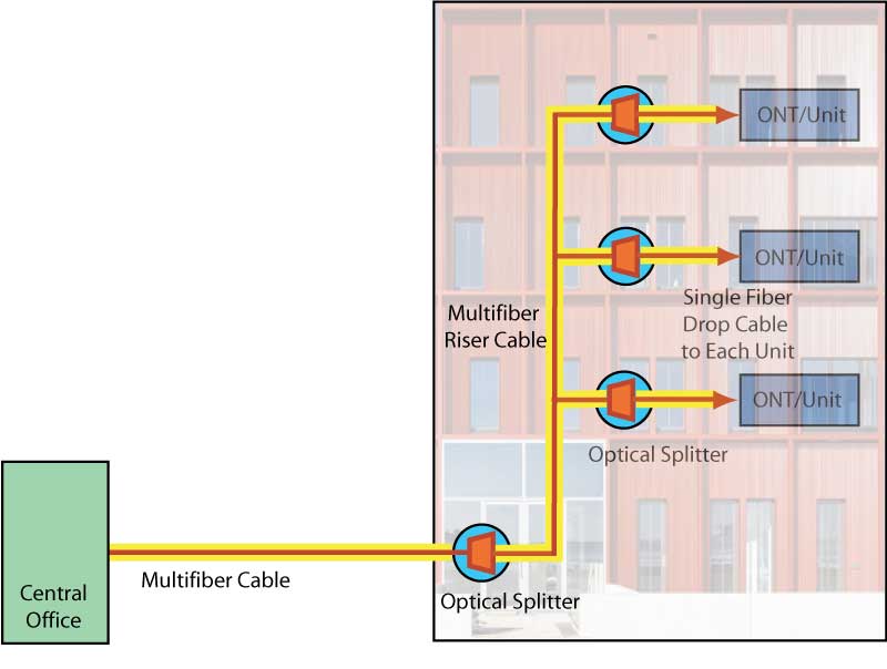
Each building should have some space
for the fiber to enter the building, have a rack or box
for splitters and connecting to cables to run to each
user. Since the PON network is passive, it is not
necessary to have power at this location, just some space
and room to work on the hardware connecting or moving
users.
A major problem in older buildings has
been finding places to run cables to each subscriber, but
new types of bend-insensitive
fiber and the special small drop cables shown above
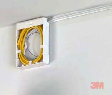
make it easy to route fibers along walls or place in
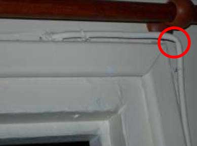
stick-on raceways on the walls. Here is an example from
Corning on how bend-insensitive fiber can be treated
without problems, but we offer a caution regarding
stapling these fibers - it could be a long-term problem
and should be avoided in our opinion.
Bend-insensitive
fiber installed in older building (L - Corning) and
hardware to stick cable on the wall (R-3M).
Cables installed in buildings should be
done neatly. Residents and owners are likely to complain
if the cabling is done badly.
Suburban FTTH Networks
Suburban networks are less dense and
installing new cables can be much easier. Some areas have
aerial infrastructure which makes installation much
easier, since aerial installation is always easier and
less expensive and special FTTH closures can allow placing
fiber hubs with splitters on poles or suspended from
messenger wires. Aerial drops are easier to individual
homes or buildings also. If the cables must be
installed underground, which is becoming more common, and
conduit space is not available, microtrenching along the
curb can simplify the installation. Handholes will need to
be located where splitters and drop closures are located.
Underground drop cables to each home
can be a problem since the cable or ducts needs to go from
a curbside handhole through the customer's lawn. Running
the cables alongside the driveway alleviates most of the
problem in many drops. If the drop cable is buried in the
lawn, there can be a problem in the future with the owner
digging up the cable because they forgot where it was
located or a landscaper or installer of invisible dog
fences starts digging. As close to the driveway as
possible is safer. Directional boring is also possible but
can be extremely expensive and has the danger of hitting
current utilities and causing damage. Not all - probably
few - owners know where their underground utilities are
located and using locating equipment is time consuming and
expensive. Gas lines are especially dangerous and can
cause fires and explosions.
From the outdoor demarcation box, a
fiber needs to be run to a location inside the home to the
location of the FTTH ONT. In any indoor installation, it
is important that the work be done neatly. A survey of the
home to locate where other cables (telephone and CATV or
satellite) enter the building and are run indoors can help
locate the easiest path for the FTTH fiber cable. As with
MDUs, the resident/owner will expect the cables to be
installed in a neat and workmanlike manner.
Rural FTTH
Rural FTTH is going to be more
expensive no matter what you do. Service providers have
used wireless drops to avoid running long fibers to each
subscriber, but the limited bandwidth, cost of the
equipment on a pole and at the subscriber (not to mention
updates) and the lifetime of powering it may prove to be
no bargain compared to running a fiber optic drop cable to
the subscriber. Most rural networks are aerial which makes
the cost much lower than underground. If the utility poles
already have low voltage cables, generally aging telephone
wires, the FTTH fiber distribution cable can probably be
lashed to the same messenger, by far the least expensive
way to install fiber.
The big problem with rural FTTH is
distance. That means longer cables and more cable and
installation costs. It also means that many networks will
exceed the length maximum of GPON while having fewer
subscribers than the number allowed by splitting. The
solution in many cases may be using the remote OLT
architecture shown above. Cables can be run alongside
rural roads and the remote OLTs installed in areas where
there are multiple users within the reach of the OLT.
Electrical utilities and coops have
rights of way and transmission lines into rural areas that
are ideal for FTTH. Many utilities already have fibers
installed, often in optical power ground wire, but
sometimes have only a few fibers available. WDM
(wavelength division multiplexing can expand the fibers
capacity if permitted. When you already have towers or
poles, installing fiber is easy with several options.
Cable can be lashed to messengers even overlashing to
current fiber or copper cables. ADSS (all-dielectric
self-supporting) fiber optic cable can be installed on
poles or towers without a messenger for long spans. There
are even methods that use lightweight cables that can be
wrapped around current-carrying conductors.
Rural telephone companies also have
rights of way and cable infrastructure. Many already run
fiber backbones. For them, the biggest obstacle is usually
financing and fortunately there are programs to provide
grants and loans for rural broadband.
Cable cost is higher for the longer
distances, but fiber optic cable is very inexpensive,
especially when compared to installation cost. The cost of
fiber itself is only part of the cable cost; the materials
used in the cable predominate for cables with fewer than
24 fibers, so buying or installing cables with fewer than
24 fibers is generally not cost effective. And installing
more fibers means that spare fibers can be leased to other
carriers - municipal/county/state agencies, telecom
companies, wireless service providers, electrical
utilities, etc. to defray the cost.
Additional
Reading on Rural FTTH
The
August
2021 issue of the FOA Newsletter compares rural
broadband today with rural electrification almost a
century ago. The situations are quite similar and the
solutions, including assisting rural electrical or telco
coops, are quite the same.
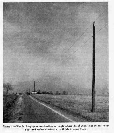
From the 1940 USDA yearbook article on rural
electrification.
Designing The FTTH Central Office or Head End
Whether you call it a central office or
head end depends on whether your background is telco or
CATV. IT types might call it the equipment room or data
center. But the location of the electronics for a FTTH
network is another design decision that requires careful
consideration and planning. The location should generally
be as central as possible to simplify and perhaps minimize
cable lengths. Space is not a big problem as FTTH PON OLTs
are not large because each OLT port serves as many as 32
or 64 users. But the design must accommodate cables and
electronics and allow for future expansion.
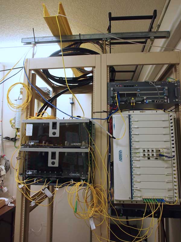
FTTH PON OLT head end for ~5,000 subscribers
The head end is also an entrance
facility, with incoming fiber optic cables from the
outside Internet connection and outgoing cables from the
OLT. Sufficient patch panel space is required for both
incoming and outgoing cables. Hardware needed includes
cable trays and management as well as rack space for the
patch panels. There will have to be rack or wall space for
the interface to the Internet service provider. This is
essentially a router with incoming signals at high speeds.
The router connects to the OLT to handle the Internet
connections.
The OLT connects the Internet to
the users by converting signals to PON protocols and
connecting users. The OLT does lots more also, including
managing users and encrypting signals for subscriber
privacy. The OLT requires a trained operator, at least
part time, to manage subscriber connections and other
regular service, so plan on having an operator attend
training by the equipment provider.
Since the subscribers require 24/7/365
operation, the entire electronics package needs
conditioned power and an uninterruptible power supply
(UPS) that can keep it going for at least 8 hours in a
power outage. Many FTTH systems also provide – or at least
recommend – a UPS at the subscriber’s site to also provide
nonstop operation.
Before
you Start, Things To Remember
Uniqueness:
Like most fiber optic networks, every FTTx installation is
unique. It must be designed for the location it is to
serve and choices on components and installation methods
should be optimized for the system. Construction and
installation methods may include every type of OSP
installation. Suppliers familiar with FTTx can advise
customers on what others have done to make
installations simpler, easier and less expensive. Most
systems prefer to use as many factory-made components as
possible as they are generally less expensive than doing
the same work in the field. New installation methods
should be considered as well to reduce costs.
Consultants:
Be wary of consultants. Consultants can be
extremely valuable in designing a FTTH system, as long as
they have relevant experience, are up to date on new
components and techniques and are highly recommended by
previous clients. Unfortunately we have seen problems with
consultants, including over-designed networks with costs
much higher than necessary, installation practices
recommended that were unnecessary or ignore newer
technology, systems designed around components that were
higher performance (and price) than necessary, and in one
case a consultant took the clients payment, went away for
a year and came back with an admission that they could not
design the network (but they kept the consulting fees.)
Contractors:
As with any fiber optic project, the quality of the
installation depends on the quality of the installer. Look
for contractors with knowledge, experience and references.
And preferably relevant certifications like the FOA CFOT.
Be especially wary of subcontractors. Any subcontractors
should have equal qualifications and be approved by the
network owner. We have seen landscape contractors with no
fiber training used as subcontractors for cable plant
installation - one cut several cables to buildings that
had been installed by a member of the FOA advisory board!
Call Before You Dig! Every day some major fiber
optic cable is cut by a contractor. The jurisdiction
issuing permits should help you with locating other buried
utilities. There is a service that helps you locate
underground utilities that may be in your construction
path. See the FOA web page on Digging
Safely.
What Fiber Do
You Already Have? Before you
design or install a new fiber optic cable plant, inventory
the fiber you have already and/or negotiate to lease fiber
where others have cables with dark (unused) fibers. Also
talk to other organizations who may need communications to
see if they want to share costs or lease dark fibers or
communications links from you. Cities, counties and states
need fiber. Utilities need fiber. Fire and life safety
organizations need fiber. Traffic departments need fiber.
Cellular companies really need a lot of fiber.
What Other
Services Can Share The Fiber? Consider what
other services than FTTH you can carry on your fiber optic
cable plant - cellular backhaul, traffic systems,
security/surveillance systems, leased fiber, etc. to
generate additional revenue. A few years ago a large
American city sent out a RFP (request for proposal) for an
urban FTTH network. The document dealt strictly with FTTH
to connect the city's citizens with fiber and ignored all
the other services the city had that already used or
needed fiber - city communications, security/video
surveillance, intelligent traffic management, public
transportation communications, wireless networks(small
cells and 5G), utility communications, etc., etc., etc.
Dig Smart -Dig
Once: This same document also covered
the difficulty of urban installation - digging up streets
already filled with underground utilities, limited space
for pedestals, few options for aerial cable and
other issues that are typical problems for urban fiber
installation. No mention of "Dig Once" to make future
installations easier. Share fibers. Use spare fibers. Use
additional wavelengths in current fiber. Consider all the
alternatives. Plan ahead - future proof is a myth, but one
can make certain decisions that will make the future
easier. If you are considering using
FTTH design software, ask to talk to customers who have
used it. Determine what you need to know first in order to
use it, e.g. GIS data on every utility pole, manhole or
handhole, subscriber location, etc. and how much training
it takes to become proficient. Will you use your personnel
or hire outsiders, and how do you evaluate them.
Cost Savings:
Fiber optic cable and components are not
expensive, but labor is. Saving money on components may
look good in first analysis, but more savings will come
from optimized designs and efficient installation
practices. More experienced contractors are more efficient
and may save costs by their speed and efficiency.
And design for the future - if you dig a trench for
anything, not just fiber but any underground utility, bury
a number of fiber ducts for future use, install cables
with more fibers than you need - lots more - fiber is
cheap, installation is expensive. The program is called
"Dig Once."
Take Rates Are
Important: "Take rates" for new FTTH networks
vary from low to high, depending on the satisfaction with
the current ISP (Internet service provider.) When Google
Fiber started in Kansas City, the take rate was high
because the current service was bad, but in later cities
when the local ISPs knew they were coming and improved
their service and/or lowered their prices, the take rate
was lower. Competition tends to drive take rates and take
rates determine the economics of the system, Know your
competition. Offering gigabit services are often the top
selling point of FTTH. Every GPON network is a gigabit
network, but subscribers can opt for slower speeds at
lower costs.
What Makes
A Successful Fiber Optic Project?
People call FOA for advice all the time. Most of the calls
deal with technical questions about products, installation
and testing. But in one call; a manager who was starting
to plan a fiber optic project wanted advice on how to
proceed. It was a long call! His basic question was “What
does it take to have a successful fiber optic project?” We
responded with 4 words: financing, commitment, expertise
and patience. (This section is repeated from the
introductory section on FTTH because it's important for
the designer and managers of a FTTH project.)
Financing: The story goes that
someone asked Neil Armstrong what he was thinking about
while sitting on top of the rocket ready to launch Apollo
11 to the moon. “Every part was made by the lowest
bidder,” was supposedly his reply. (The same quote has
been attributed to most early astronauts!)
Fiber optics are not necessarily
expensive; in fact, fiber has been used so widely because
it is the least expensive communications medium in
virtually all projects. But fiber optic projects may
require a lot of construction which makes the project
expensive. Like all other projects, it never pays to cut
corners. Planning and running the project properly is what
saves money, trying to cheapen the project. Not all jobs
should go to the lowest bidder, unless they meet all the
criteria for a qualified bidder. Likewise, one needs to
ensure that when a project starts, there are funds
available to complete the job properly, including some
extra for unplanned changes or modifications.
Commitment: Just like having
sufficient finances to compete the project, one needs a
commitment to finish the job once it is started. Changes
of management or changes in governments often lead to
confusion or even modifying a project in midstream. There
is nothing wrong with making changes based on what learns
as the project progresses; it may even involve greater
efficiency or cost savings, but arbitrary changes may
jeopardize the project's timetable, completion or even its
usefulness.
If the project is under the auspices of
a government entity, changes in administration or
management that causes changes in a project will
invariably make it more expensive and may jeopardize the
success of the entire project. Ideally, the personnel who
propose, design and plan the network should see it to
completion.
Expertise: Fiber requires
expertise and experience. It's obvious the installers need
to know what they are doing, but in reality, so must the
managers who work for the organization that is contracting
for the work. There are many instances of projects where
the managers signed off on the project when it was
incomplete or improperly installed. The only way to
properly manage a project is to understand every aspect of
it well enough to know if it is being done properly and
when it is actually complete.
Planners, designers, contractors and
installers should all be trained and certified
as well as being experienced with good references. That
holds doubly so for consultants. In many places, to be a
consultant or cabling contractor means little other than
registering as a business and advertising your services.
Some of the problems we've seen with outside services,
include consultants who took contracts, spent time on a
project, then told the customer they could not help them
with the project, but kept the money.
We have seen contractors doing shoddy
installations, ruining expensive fiber optic cable during
pulling and leaving jobs half done but getting paid
because the customer knew no better. One of the biggest
problems is subcontractors. A contractor with good
credentials gets the job but subcontracts some of the work
to a contractor who will do the work at a lower price, but
does not have the training or experience (or motivation)
to do it right. In your contract with an installer, we
recommend a clause giving the project manager
responsibility for evaluating and approving all
subcontractors.
The manager must know better to prevent
problems. FOA also has pages on what
the manager needs to know.
Patience: From concept to
acceptance, a typical OSP fiber project can take 2-5 years
and a premises project 1-2 years. It depends on the size
of the project, the time to properly design it, create
project paperwork, get permits, buy components, hire
contractors and properly install it. Proper
workmanship takes time and is not easily rushed. Saving
time generally means cutting corners and that is often the
cause of the problems encountered. Take your time, plan,
design, select, install, test and document your network
properly.
And by the way, "future proofing" is a
myth! Who would have known in 1990 how ubiquitous the
Internet would be today? How reliant we could be on
smartphones other mobile devices? How many workers would
be working remotely or using videoconferencing for
meetings? Technology moves too fast and is too disruptive
for anyone to make reliable predictions. The IBMer who
developed MRP - the original company organizational
software - used to tell everyone, "A forecast is wrong
from the moment it is made." Plan for the future, but
assume you will upgrade, change directions, etc. driven by
new tech and changes in the world around us.
- Technical
Information on FTTX From The FOA
Online Guide:
- FTTH
Introduction
- FTTH
Architectures,
- FTTH
in MDUs (Multiple Dwelling Units)
- FTTH
PON Standards, Specifications and Protocols
- FTTH
Design
- FTTH
Installation
- FTTH
Customer Premises Installation
FTTH
Network Testing
FTTH
Case Studies: Do-It-Yourself FTTH
FTTH
Project Management
Migration from GPON to 10GPON
- The
Fiber Optic Association Fiber To The Home Handbook:
For Planners, Managers, Designers, Installers And
Operators Of FTTH - Fiber To The Home - Networks
The
Fiber Optic Association Fiber To The Home
Handbook Available
in paperback or as an eBook on the Amazon
Kindle Available
direct from Amazon.com,
local booksellers and other distributors.
- Training
& Certification
Fiber
U Online FTTx Self Study Program (free)
- FOA
Certification Overview
FOA
FTTx Certification Requirements
FOA-Approved
Training Programs
Table of Contents: The
FOA Reference Guide To Fiber Optics
|
