FTTH
in MDUs (Multiple Dwelling Units)
When we normally talk about FTTH, we assume we are
installing the fiber to a “home” where it terminates in a
optical line terminal (OLT) and services (voice, data and
video) are delivered inside the subscriber’s home. But
since we may have detached single-family homes, row houses
or units in a large building, the situations can be quite
different, requiring different architectures and
installation practices. We should add that office
buildings are often similar to MDUs, with the exception
that floor plans are generally more flexible and units are
larger, but the concepts are similar.
Let’s assume we have fiber to the building, then
what’s next? We must decide how to deliver broadband to
each unit in the building and then inside the unit. What
are the options for delivering services to each unit from
the entry facility?
Options for connecting each unit in the building include
using:
1. Currently installed phone lines using xDSL technology
2. Currently installed CATV or satellite coax using cable
modem or MOCA (Multimedia Over Coax Alliance) technology
3. Installing wireless access points at appropriate points
in the building connected by Ethernet as is usually done
in hotels
4. Installing new category-rated UTP cable to each unit if
it is within the 100m distance limit and use Ethernet
5. Installing new coax cable to each unit and use cable
modem or MOCA
6. Installing fiber to each unit and mounting the ONT
(Optical Network Terminal) at or inside the unit
Options 1 and 2 eliminate the need to install new cabling
but assume the current cables are in good enough condition
to carry the signal bandwidth required. Options 3, 4 and 5
require installing new cables and furthermore, option 3
assumes adequate bandwidth over the wireless for typical
users. It would probably be overwhelmed by video users.

And options 1 through 5 require considerable investment in
electronics, space to locate them and quality
uninterruptible power at the building entrance facility.
The actual network architecture is influenced by the
choice of electronics. ONTs are available for single users
or multiple users, allowing one to distribute ONTs in a
building, for example to serve all the units on one floor
with copper cables. However, these multi-user ONTs are
going to divide up available bandwidth among the number of
units served, perhaps not a problem if the system if
offering Gb/s services to the ONT, but potentially a large
problem, even today but certainly in the future, if the
bandwidth allocated to multiple users is much lower.
With option 6, we would generally assume a GPON or EPON
system, although a point to point (P2P) system can be
used. In the case of a P2P system, fiber to the unit would
entail either a switch in the MDU building itself or a
large fiber count cable back to the central office or
nearest switch.
Assuming a GPON or EPON network, option 6, installing
fiber to every unit, has several variations that can be
used and all have one big advantage: no matter how big the
building and how many units, the size of the entrance
facility is minimized and no power will be required except
at each individual ONT at the unit. The options start with
where to place the PON splitters to optimize the cabling
and installation then what kinds of cabling and hardware
are needed to simplify the installation.
Options for connecting units with fiber include these
architectures:
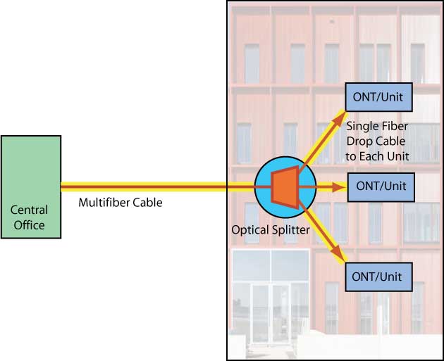
1. PON splitters can be outside the building in a service
provider facility and large fiber count cables brought
into the building, then broken out in premises drop cables
to units. This architecture also supports a P2P (point to
point, not PON) system.
2. PON splitters can be located in the entrance facility
of building, minimizing the fiber count into the building,
then drop cables run from that point to each unit.
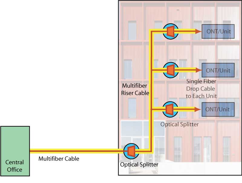
3. PON splitters can be cascaded from an initial PON
splitter in the entrance facility to individual splitters
on each floor or area of the building, supporting units on
that floor or area.
4. Theoretically, one could have a OLT (optical line
terminal) installed in the building connecting to
splitters distributed throughout the building or
buildings. Sonce these units support thousands of users,
dedicating a unit to one building would probably not be
done except in large complexes.
The actual architecture will be influenced by the design
of the MDU building and where and how it is convenient to
install components for the FTTH systems. Component cost
may need to be compromised to facilitate installation and
reduce cost there.
MDUs come in many varieties, of course, including rows of
attached units, low-rise MDUs with only a few levels of
units and high-rise MDUs. The first two are more
horizontally distributed while high-rise buildings can
have both many vertical levels and small to large
horizontal distribution depending on the height and size
of the building and the size of the units.
While some older units will allow cables to be installed
on the exterior of the building, that is probably not
going to be allowed on more modern buildings nor on
high-rise buildings. However, most buildings will have
facilities for cabling even if they are so old that they
only had electrical and phone services originally.
Like any FTTH system, a “greenfield” installation offers
much more flexibility for designing a building that
simplifies cable and hardware installation. Plans can be
made to include cable conduit and/or cable trays and
facilities for other network hardware. But most large MDUs
have provision for cabling for services like phones and
CATV, perhaps even Internet if built more recently, that
offer good options for FTTH fiber installation.
The PON splitter can be located in the building entrance
facility and drop cables run to each unit. This mimics
most phone wiring and pathways may be available to run
drop cables. It uses more fiber and/or cables but does not
require mounting as much hardware around the building nor
splicing and/or termination.
One reasonable option is to use cascaded splitters. The
first splitter can be located in the entrance facility
with multiple fibers going out to the separate floors
where a splitter is installed to serve the floor.
Alternatively, the first splitter can be placed on one of
the served floors. If one has 8 units per floor, a total
of 4 floors can be handled on 32 split ratio system with a
4 way splitter feeding 8 way splitters on each floor.
Likewise, one could use a first splitter of 8 ways to
serve 4 floors. Or a 16 way first splitter would serve 4
floors. The best option probably depends on the building
and how cabling would be installed.
This may not be a good choice if the owner of the building
wants to offer several service providers for FTTH. It
limits the connection to one provider for the building. A
better choice would be to have a fiber running to each
unit from the entrance facility so that fiber could be
plugged into equipment of the service provider they
choose.
Recent developments on distribution and drop components
make MDU installations easier. Perhaps the biggest
development was bend-insensitive fibers that allow the
manufacture of drop cables in extremely small sizes that
can be run along wall or ceiling junctions, around
corners, placed inside baseboard or molding and even made
with an adhesive surface that can be stuck directly on
walls. Bend-insensitive fibers also allow the manufacture
of small cables that allow opening at any location to
break out one or more fibers for termination at that point
and allow the whole cable to continue to another location.
Small boxes or closures are available that contain
couplers and patch panels allowing drop cables to be
terminated with prepolished/splice connectors, either
fusion- or mechanical-spliced, to complete the
connections.
Like any fiber or cabling installation, the actual project
will be unique but be able to incorporate ideas that
worked well in prior projects. If the building project is
in the design stage itself, knowledgeable fiber optic
designers can provide feedback that will make the
installation easier, neater and much less expensive.
The most important part of the design of a project in an
existing building is a “walk through” to familiarize
yourself with the building. Inspect for entrance
facilities, cabling pathways and locations for equipment
on every floor. Look at several units to see where it is
feasible to enter the unit and place equipment. Having a
familiarity with the building itself will make choosing a
design much easier.
Another issue, of course, is the take rate for FTTH
connections., which can affect planning as well as the
ultimate cost. On older buildings, units may already have
CATV or satellite connections and not be interested in
FTTH, so one cannot assume a 100% take rate. The building
owner can survey those living in the units to determine
the take rate for planning purposes, but one also has to
assume some number of future additions in doing the
design. New construction may be easier, as the
developer/builder may decide to make FTTH a selling
feature and provide it to all the units.
- Technical
Information on FTTX From The FOA
Online Guide:
- FTTH
Introduction
- FTTH
Architectures,
- FTTH
in MDUs (Multiple Dwelling Units)
- FTTH
PON Standards, Specifications and Protocols
- FTTH
Design
- FTTH
Installation
- FTTH
Customer Premises Installation
FTTH
Network Testing
FTTH
Case Studies: Do-It-Yourself FTTH
FTTH
Project Management
Migration from GPON to 10GPON
- The
Fiber Optic Association Fiber To The Home Handbook:
For Planners, Managers, Designers, Installers And
Operators Of FTTH - Fiber To The Home - Networks
The
Fiber Optic Association Fiber To The Home
Handbook Available
in paperback or as an eBook on the Amazon Kindle
Available
direct from Amazon.com,
local booksellers and other distributors.
- Training
& Certification
Fiber
U Online FTTx Self Study Program (free)
- FOA
Certification Overview
FOA
FTTx Certification Requirements
FOA-Approved
Training Programs
Table of Contents: The
FOA Reference Guide To Fiber Optics
|
