|
Insertion
Loss
Testing the Installed Fiber Optic Cable Plant With A Test Source and Power Meter
 Typical
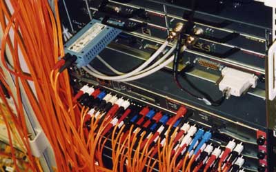
fiber optic cable plants are composed of a backbone cable
connecting patch panels and several short jumper cables
which connect the equipment onto the cable plant. Premises
cabling systems look like the photo to the right,
where the backbone fiber is terminated in wiring closets and
short jumpers connect wall outlets or directly to the
equipment. These installations often have no splices at all,
since distances are short. Premises cabling, which is short
and often lower speed, is often multimode fiber, unless the
network speed is >10Gb/s as in data
centers, uses a GPON
passive optical LAN or is shared with a cellular
distributed antenna system. Typical
fiber optic cable plants are composed of a backbone cable
connecting patch panels and several short jumper cables
which connect the equipment onto the cable plant. Premises
cabling systems look like the photo to the right,
where the backbone fiber is terminated in wiring closets and
short jumpers connect wall outlets or directly to the
equipment. These installations often have no splices at all,
since distances are short. Premises cabling, which is short
and often lower speed, is often multimode fiber, unless the
network speed is >10Gb/s as in data
centers, uses a GPON
passive optical LAN or is shared with a cellular
distributed antenna system.
OSP (outside plant) cable plants look similar, but the the fiber is all
singlemode and cable runs may be long, requiring splices
every 2-4 km. In addition, the fibers are not terminated
directly, but high quality factory made pigtails are spliced
onto the backbone cable. The process of testing any fiber
optic cable plant during and after installation includes all
the procedures covered so far.
To
thoroughly test the cable plant, one needs to test it three
times, a continuity test of the fiber optic cable on the
reel before installation, insertion loss of each installed
segment and complete end to end loss. One should test the
cable on the reel for continuity before installing it, to
insure no damage was done in shipment from the manufacturer
to the job site. Since the cost of installation usually is
high, often higher than the cost of materials, it only makes
sense to insure that one does not install bad cable. It is
generally sufficient to just test continuity, since most
fiber is installed without connectors and then terminated in
place, and connectors are the most likely problem to be
uncovered by testing for loss. However, if any damage is
visible on cable reels, OTDR testing may be needed to verify
the cable is still good.
After
installation and termination, each segment of the cable
plant should be tested individually as it is installed, to
insure each connector and cable is good. Finally each end to
end run (from equipment placed on the cable plant to
equipment) should be tested as a final check. Measured loss
should be compared to the calculated
loss budget for the cable plant to determine if the
measured loss is acceptable.
What
is Insertion Loss?
Optical
loss is a term used in many contexts in fiber optics. It
simply means a reduction in optical power, for example the
loss caused by a component or an entire cable. The
component could be a length of fiber, a splice, a
connection made between two connectors or a passive
component like an attenuator, splitter or switch. The
cable could be a patchcord or an installed cable plant.
The
primary test for these is an insertion loss test, test
that uses a test source and optical power meter to measure
the difference in power when the component is inserted in
the test setup. For a cable plant, the insertion loss test
uses a test source and power meter to simulate the
transmitter and receiver of a communications link.
Variations of this test are used for practically every
loss test in fiber optics.
Optical
loss in a fiber optic link. The meter shows the decrease in
optical power in the pulse as it traverses the fiber.
The goal of an insertion loss test is to simulate link
operating conditions by using a test source to launch power
into the fiber or cable under test and a power meter to
measure the loss at the other end. That requires creating
launch conditions from the test source that are similar to
transmitter sources and using the power meter to measure the
power from the source before and after the component or
cable is inserted in the test setup. How this is done is the
subject of many standards in fiber optics that ensure the
test results from laboratories, manufacturers, installers or
users are comparable.
Why
is this test called an "insertion loss" test?
The name comes from the fact that one performs the test by
inserting the components under test between a test source
and a power meter. The most obvious version of this test is
the method used by manufacturers to evaluate connector or
splice loss as shown in the diagram below. It can also be
used to measure the attenuation of optical fiber.
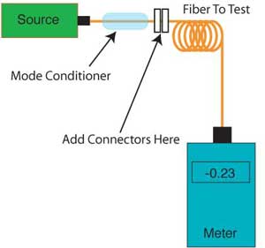
Insertion
loss test for a fiber optic connector.
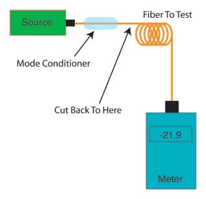
Cutback
test to measure the attenuation coefficient of optical
fiber.
This is the insertion loss test used by manufacturers for
evaluating the performance of connectors or splices. This
test connects the test source to a power meter over an
optical fiber. Often this test is done with bare optical
fiber with the connection to the power meter using a bare
fiber adapter. The meter and source are turned on and a "0
dB" reference is set.
To test the component the fiber is cut and a pair of
connectors or a splice is inserted in the fiber and the
change in power measured. The change in power indicates the
loss generated by the insertion of the component. When
evaluating a new component, manufacturers may do hundreds or
thousands of these tests to determine the average
performance of the component that they specify in their
product datasheets.
For tests involving multimode fiber, the test results are
highly dependent on the test setup, particularly the modal
distribution launched into the fiber used in the test. Test
sources can have significant variations in modal
distribution so it is important to include some form of
modal conditioning in the test fiber. Modal conditioning and
other issues that affect all multimode tests will be covered
in a section below on test conditions.
Note: It Is Connection Loss, Not Connector Loss. It's common in fiber optics to talk about
the loss of a connector, but a connector loss is measured
when mated to another connector. In fact, a single
connector has no loss because a connector is defined as a
component that allows making connections between two
fibers or connects one fiber to an active device like a
transmitter or receiver. The correct term is "connection
loss" because it is the loss of a mated pair of
connectors. In practice, we assign a loss to a connector
by testing it against a reference connector, as you will
see when we discuss single-ended insertion loss testing
below.
Testing Cables And Cable Plants With Connectors
The most common tests involve testing fiber optic cable
plants, patchcords and other components that have connectors
on each end. These are tested with a test source and power
meter with reference test cables to connect to the component
under test. There are two versions of this test, a double
ended test and a single ended test.
The double-ended test is the standard test for installed
cable plants that allows testing the entire cable plant
including the connectors on each end. It is a simulation of
the loss an actual transmission system will see when
connected to the cable with patchcords. Here is the block
diagram of the test:
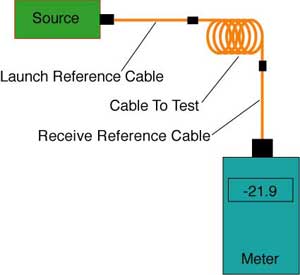
Standard cable plant test, double-ended with launch and
receive cables
The source has a launch reference cable because it launches
power into the component under test. The power meter has a
receive reference cable because it receives the power after
the component has been inserted. Each of these mate to one
end of the cable under test to measure the connection loss
on both ends, hence the name "double-ended." The
cable under test is sometimes called the "permanent link," a
reference to the name of the installed cable in UTP copper
cable testing.
The "0 dB" reference measurement is made with the test
source and power meter with their reference cables using one
of three different but acceptable methods, depending on the
types of connectors on the test equipment and the cable
plant. The
reason for the existence of three methods is the
compatibility of test equipment to the cable plant; whether
the test equipment has connector interfaces that allow
direct connection to the cable under test.
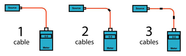
Three ways to set a "0dB" reference for insertion loss
testing.
Which
method is used depends on the connectors on the cable plant
you are testing and the connector interfaces on your test
equipment. (And some history about how different companies
defined testing.)
The
options for use of these three methods are:
- If
the test equipment has connectors compatible with the
cable plant, a one-cable method can be used.
- If
the test equipment does not have connectors compatible
with the cable plant, a two- or three-cable method must
be used.
- If
the test equipment does not have connectors compatible
with the cable plant and/or the connectors are the “plug
and jack” or “male, female” type like the MPO multifiber connector, a three-cable method
must be used.
The insertion loss test then measures the loss generated by
adding the cable under test. The value measured is called
the loss of that particular fiber optic cable. The loss can
be compared to the calculated
loss budget to see if the cable plant meets
specification.
Testing
the complete cable plant is done per standard test
procedures, e.g. FOA
Standard FOA-1, TIA OFSTP-14 for multimode fiber or
OFSTP-7 for singlemode, which use the same procedures or
ISO/IEC 61280, ISO/IEC 14763, etc. These
standards offer 3 different ways to set a "0 dB"
reference and cover the peculiarities of multimode
fiber in detail. Information for multimode cables covers
the problems of controlling
mode power distribution, but the same procedures
apply for singlemode fiber, less the concerns expressed
for mode power distribution errors.
For
multimode fibers, testing is now usually done at 850 and
sometimes also at 1300 nm, using LED sources with some
control over mode power distribution. This will prove the
performance of the cable for every datacom system,
including FDDI and ESCON, and meet the requirements of all
network vendors.
OFSTP-7
was written for singlemode fiber cables. Testing is
usually done at 1310 and 1550 nm, but 1625 nm is sometimes
required also. The1550 nm testing will show that the cable
can support wavelength division multiplexing (WDM) at 1300
and 1550 nm for future service expansion. In addition,
1550 and 1625 nm testing can show microbending losses that
will not be obvious at 1300 nm, since the fibers are much
more sensitive to bending losses at the longer
wavelengths.
If
cable plant end to end loss exceeds total allowable loss,
the best solution is to retest each segment of the cable
plant separately, checking suspect cables each way, since
the most likely problem is a single bad connector or
splice. If the cable plant is long enough, an OTDR may be
used to find the problem. Bad connectors must then be
repolished or replaced to get the loss within acceptable
ranges.
Testing Patchcords
One can also do a variation of the insertion loss test with
only a launch cable, called a "single ended" test, that only
tests the connector on the source end of the cable. This
test is often used to test patchcords since it allows the
measurement of the connectors on each end separately, a more
rigorous method of testing these short cables.
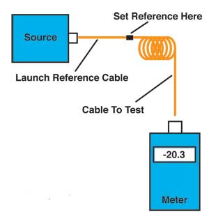
Fiber optic patchcord test, also called "single-ended" test
The single ended test looks like the double ended test
except there is no receive reference cable. The cable under
test is mated to the connector on the launch cable and the
power meter. The "0 dB" reference measurement is made with
the test source, a launch reference cable and the power
meter, exactly like the one cable reference for double ended
insertion loss tests.
The output of the launch cable is the 0 dB loss reference,
so for short cables like patchcords, the measurement is
basically the loss of the connection between the launch
cable and the test cable. The test cable can be reversed and
the connector on the other end tested separately. This test
is used on patchcords because it allows testing each
connector individually, ensuring that both connectors meet
specifications. If the cable were tested with the double
ended test, one would measure a total loss of both
connectors and could not identify if one connector were out
of specification.
Choosing Appropriate Test Equipment
In order to perform an insertion loss test, it is necessary
to have appropriate equipment for the cables or cable plant
under test. Whether one uses a test source and power meter
or optical loss test set (OLTS), the equipment must be
compatible with the test requirements.
The fiber optic power meter used for insertion loss testing
should be calibrated at the wavelength of the test source
being used. The meter should have a connector adapter
compatible with the connectors on the cable plant being
tested. Having a special "dB" range that will allow setting
a "0 dB" loss reference power level will simplify testing.
An OLTS will offer both source and power meter for loss
testing at the appropriate wavelengths. The requirements for
the source for modal conditioning (see below) and
compatibility of the instrument to the connectors on the
cable plant being tested may have to be accommodated by the
reference test cables.
Test Source Wavelengths
For multimode fiber, the test source should be a LED at 850
nm that is the wavelength used for virtually all multimode
communications systems. There is an option for testing at
1300 nm with a LED also, but there are few systems today
that operate at that wavelength so testing at that
wavelength is generally unnecessary. You will find some
references to using 1300 nm testing to find stress on the
cable, since multimode fiber is much more sensitive to
bending losses at 1300 nm. But even that reason is no longer
relevant in most cases because most multimode fiber is of
the bend-insensitive (BI) type. Finding stress areas in
cables can be tricky anyway, but if the cable is long
enough, an OTDR that offers both 850 and 1300 nm testing is
a better instrument for finding the location of the loss.
While most 850 nm multimode systems operating over OM3 or
OM4 fiber today use VCSEL sources (vertical cavity
surface-emitting lasers), these sources are not recommended
for use as test sources due to the unpredictable mode power
distribution of individual devices. Instead, standards now
call for sources with mode power distribution or
conditioning the output of the source and its launch cable
to approximate an ideal VCSEL mode condition. This will be
covered below in reference cables and again in the section
on mode conditioning for multimode fiber testing.
Singlemode fiber is tested with laser sources, similar to
the devices that will be used in the communications systems
which operate over the fiber. Singlemode fiber will be
tested with 1310 nm and/or 1550 nm lasers depending on the
cable plant to be tested. Short links, from hundreds of
meters in a data center or building up to 20 or 30 km in
metro networks, are always tested at 1310 nm and often at
1550 nm if wavelength division multiplexing (WDM) or passive
optical networks (PONs) like FTTH are planned for use on the
link. Long links are tested at 1550 nm to match the
wavelengths of networks using them.
There may also be a reason to test short singlemode links at
1550 nm to find stress loss in a cable plant caused by
installation. But as mentioned above, this is not relevant
if bend-insensitive fiber is being used in the link, common
today in high fiber density cables. Also testing at 1550 nm
for finding stress is more relevant to ODTR testing where
the cause of the stress loss can be determined.
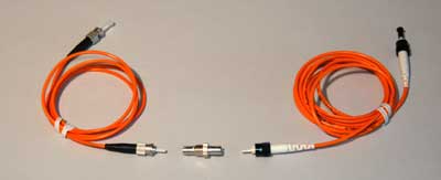
Reference Test Cables
Just as important as the choice of test equipment is the
choice of reference
test cables for the launch cable and receive cable.
The basic requirements for test cables is that they be about
1 to 2 meters long, match the size of fiber in the cable
plant under test and have connectors compatible to the
connectors on the cable plant. Multimode graded index fiber
in test cables should be 62.5/125 for OM1 cable plants or
50/125 for OM2, OM3, OM4 or OM5 fiber cable plants. There
are no significant differences in types of 50/125 fiber so
any type of this size fiber can be used to test any other
type. Today most of the multimode graded index fiber is bend
insensitive (BI) fiber. Many standards recommend not using
BI fiber for reference test cables even if testing BI fiber
cables, but this may not be possible. We'll discuss BI fiber
in the section on modal conditioning for multimode
fiber. When testing step-index multimode cable plants
using plastic optical fiber (POF) or plastic coated silica
fiber (PCS), one must likewise choose a matching fiber for
reference cables.
The connectors on the test cables should be PC polished
(physical contact) and should be of very high quality,
determined by having low loss when tested against each other
in the single ended test mode. One should use low loss
patchcords, typically under 0.3 dB, so the test results will
be consistent. With use, the connectors will wear, even when
cleaned frequently. If the patchcords exceed 0.5 dB over
time, they should be replaced. Careful repolishing with
diamond polishing film by an experienced tech may bring the
loss back down. Or the cables should be replaced.
The new TIA OFSTP-14 and ISO/IEC 61280-4-1 standards for
multimode call for 2 meter long "reference quality" test
cables with connector loss of 0.1 dB. The standard explains
that this may require special cables with selected fibers
and selected connectors as well as higher quality mating
adapters such as those used for singlemode fiber with
ceramic mating adapters. For singlemode fiber the loss
specified is 0.2 dB.
There are very few sources of "reference quality" test
cables. Multimode cables with losses of 0.1 dB will degrade
with use, showing the effects of the many mating cycles
required when testing in the field. Using high quality
cables with relatively loss is the practical solution.
Cables with loss of 0.2 up to 0.5 dB maximum are generally
adequate for testing multimode fiber.
The launch reference cable combines with the test source to
create the modal conditions used for testing. If the source
modal conditions are not specified, and they rarely are, the
modal conditions can be modified by the user using special
patchcords or modal conditioning on the cable itself. This
is discussed in the section on modal conditioning below. Do
not ignore modal conditioning in multimode testing. When
coupled into multimode fiber, LEDs typically have higher
modes than are specified by test standards. Mode
conditioning will remove those higher modes and tests will
be more consistent and will consistently show lower loss.
Singlemode reference cables should also be high quality
cables. The connectors must also be compatible to the type
of connector on the cable plant being tested, e.g. PC
(physical contact, color coded blue) or APC (angled physical
contact, color coded green.) For singlemode fiber "reference
quality" test cables, the loss specified is 0.2 dB. High
quality singlemode patchcords should be 0.3 dB or less so
this limit is not unreasonable.
Singlemode does not have mode conditioning standards like
multimode fiber, but short launch patchcords connected to a
typical laser source may support 2 modes for short distances
and that can affect measurement results. To ensure the
launch is singlemode, a mode filter made with a small loop
of fiber 40 to 60 mm diameter (1.6 to 2.4 inches) in the
launch cable will ensure singlemode launching at the end of
the cable.
More on reference cables.
Test Conditions For Accurate Insertion Loss Testing
As with any testing, to reduce measurement uncertainty, it
is important to consider and as, far as possible, control
test conditions. It is important to understand all the
contributions to measurement uncertainty and how their
effects can be minimized by the test operator. Many sources
of measurement errors are not controllable by the user. They
depend on the manufacturer of the test equipment, optical
fiber, connectors, etc. and their quality control.
The first and most important issue is to decide which
reference method to use (1, 2 or 3 cables) and record that
with the test data. Since the test results change
considerably with the choice of reference method, this is
very important information to record. After setting the "0
dB" reference, it is important to not disconnect the
reference launch cable from the source. The connection
between the source and cable can change if it is
disconnected and reconnected invalidating the "0 dB"
reference set.
Secondly, monitor the type and condition of all the test
reference cables. This is probably the biggest cause of
random errors in testing. Of course the fiber in the
reference cables must match the type in the cables being
tested and the connectors must be compatible. The condition
of the connectors on the reference cables should be
inspected for cleanliness and damage, cleaned and inspected
again to ensure proper cleaning. Then the reference cable
connectors should be tested against each other to ensure
they are still low loss. As the loss increases from more
testing, replace the cables or refurbish the connectors by
repolishing using diamond film.
The connections to test cables have another important
component, the mating adapter used with connectors. All the
single fiber connectors use mating adapters to align the
ferrules. These adapters are available in several types,
depending on the alignment sleeve for the ferrules. Some
inexpensive mating adapters use plastic alignment sleeves
that should never be used for testing. These sleeves wear
out quickly and leave dust and residue on the connectors.
The acceptable mating adapters use metal or ceramic
alignment sleeves. Metal sleeves work for hundreds of tests
but ceramic sleeves will last many times longer and leave no
residue.
Test equipment used for insertion loss testing should be
checked and power meters calibrated regularly, according to
manufacturers specifications. When making tests, the biggest
problems are with sources. First of all, the source needs to
be stable; if its output power drifts, the 0 dB reference
will be lost and all tests will be wrong. You can test your
own source by connecting it to a meter with a patchcord and
turning it on. Note how long it takes the output to be
stable and use that time as a warmup time when setting up to
make tests. If the source is not stable over time, varying
more than 0.1 dB after warmup, it should be checked or
replaced with a more stable source.
The second issue with sources is modal
conditioning. This is mainly a multimode fiber and LED
test source problem, but even single mode sources with
lasers can have modal problems. The user should ensure that
multimode launch cables have proper mode power distribution
since that can affect the loss measured significantly. Using
a simple mandrel wrap and checking the modal distribution
with a HOML (higher
order mode loss) test as described below will greatly reduce
measurement errors. For singlemode fiber, a simple loop mode
filter is all that is needed. With all reference cables, be
careful to not stress them during the tests as that can
induce loss that will change the 0 dB reference and or
create changes in the modal distribution.
The technician performing the tests should be experienced in
the process, familiar with the procedures and conduct every
test in the same manner. Even small issues like stress on
reference cables can make big differences in measurements.
If reasonable precautions are taken, what is the likely
accuracy of loss measurements? Experience has shown that
typical measurements have an uncertainty of approximately
+/-10% of the measured value in dB. Thus a 2dB loss has an
estimated uncertainty of +/-0.2 dB.
Troubleshooting Hints
Most problems with high cable loss are caused by bad or
dirty connectors, high loss splices or stress loss in the
cable caused during installation.
The first step is connectors should be inspected with a
microscope for dirt, scratches cracks, or other damage and
thoroughly cleaned. Visual fault locators can check for
continuity, proper connections and, if the cable jacket
permits, high loss bends or breaks.
If you have high loss in a single cable with connectors on
each end, you can reverse it and test in the opposite
direction using the single-ended test method. Since the
single ended test only tests the connector on the end
connected to the launch cable, you can isolate a bad
connector this way. The bad connector is the one at the end
mated to the launch cable when you measure high loss.
High loss in the double-ended test should be isolated by
retesting single-ended and reversing the direction of test
to see if the end connector is bad. If the loss is the same,
you need to either test each segment separately to isolate
the bad segment or, if it is long enough, use an OTDR.
What
About OTDR Testing?
The OTDR is better at troubleshooting problems than making
quantitative measurements because it uses a different test
method. However it can be invaluable at testing in certain
situations and troubleshooting. Read
more about OTDRs here.
This page was taken from the FOA
Guide To Fiber Optic Testing, Chapter 8.
Recommended
reading:
FOA
Standard FOA-1
Reference Cables.
5
Ways to test a fiber optic cable, 3 different ways to
set a "0 dB" reference
Testing
cables with different types of connectors
Accurately
Testing Fiber Optic Cables
The
Math of Insertion Loss Testing - Reference Methods
More
on OLTS/OTDR testing.
Videos
on cable testing on the FOA Channel on 
|
