Accurately Testing Fiber
Optic Cables
Note On Terminology: You need to know what we
mean when we say accurate that the measurement made
gives a value close to the real value. Another term
often misunderstood is "precision" which means if you
make the same measurement over and over, you get the
same value, but that value may not be accurate.
Standards people prefer to talk about the uncertainty
of the measurement because its practically impossible
to know what the real value is, but it is possible to
determine how much error is likely in any given
measurement. With apologies to those people, Im going
to use the term accuracy because everyone uses it more
commonly.
The customer for a fiber optic cable
installation will require documentation of test results
before accepting and paying for the work. This obviously
leads to certain but often conflicting requirements on the
part of the contractor doing the installation. Testing
takes time, so completing all the tests in the minimum
time means more profit. Testing, however, needs to be done
carefully to ensure the measurements are accurate1, and
that can take time. Accurate testing, however, will ensure
that no good cables are rejected and no bad ones missed,
so the contractor will not have to repair what are really
good cables and get callbacks on bad ones.
Lots of time and cost - can be saved if
the contractor and installers know the proper measurements
that need to be made, understands how to make those
measurements correctly, has the proper tools, keeps them
in good condition, has them calibrated regularly and knows
how to use them efficiently. It is also the duty of the
contractor to convey to the customer what is being done is
in line with industry convention and standards. Learning
the background and the issues concerned with making
accurate measurements can save lots of problems and
money.
Industry committees spend massive amounts of
time and energy developing standards that ensure accurate
testing. However, those standards are generally written
for manufacturers, not users, so the task of translating
standardese the language they are written in into
understandable English is left to the manufacturers
themselves and technical educators in articles like this.
This tutorial will give you insight into what tests are
required, what problems are inherent in testing multimode
fiber, how measurement techniques differ and how to
interpret the results of testing and document them.
What Tests Are Available,
Needed and Performed?
All fibers in a cable plant should be tested
at least for continuity, proper end to end connections
and, most importantly, loss. How each of these tests are
performed depends on the installation type, required
standards and the actual layout of the components in the
cable plant.
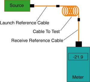
Actually, there are five
industry standard ways of testing the loss of a fiber
optic cable three for insertion loss and two for
OTDRs depending on how you use reference test cables for
your setup. Insertion loss testing with a test source and
power meter with reference cables (right) can use 1, 2 or
3 reference cables to set the zero dB loss reference for
testing and each way gives a different loss. Generally
standards prefer the 1 reference cable loss method, but it
requires that the test equipment uses the same fiber optic
connector types as the cables under test. If the cable has
different connectors than the test equipment (e.g. LCs on
the cable and SCs on the tester), it may be necessary to
use a 2 or 3 cable reference, which will give a lower loss
since connector loss is included in the reference and will
be subtracted from the total loss measurement. Any of the
three methods are acceptable, as long as the method is
documented. Be careful, however, as most network link
losses assume a 1 cable reference, which can affect the
acceptance of the cable.
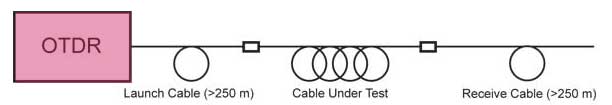
OTDRs (Figure 2) always require a
launch cable for the instrument to settle down after
reflections from the high powered test pulse overloads the
instrument. OTDRs have traditionally been used with long
distance networks where only a launch cable is used, but
this method does not measure the loss of the connector on
the far end. Adding a cable at the far end allows
measuring the loss of the entire cable, but negates the
big advantage of the OTDR, that it makes measurements from
only one end of the cable.
First of all, to look at
test requirements, we'll divide the topic by
installation type: Outside Plant (OSP) or Premises.
Testing Outside Plant
Cables
OSP cables are typically long
distance singlemode cables that are installed in short
sections, usually 5-12 km max depending on the cable size,
since the bulk and weight of the cable determines how long
is the longest cable that can be installed. Shorter
lengths may be common in urban or campus networks, as
cable is installed between junction points which are
determined by the geography of the cable plant. Since
shorter lengths of cable are spliced together,
verification of the splices is important and is usually
done with an OTDR test during the installation process.
Once installation is complete, end-to-end insertion loss
is done with a test source and optical power meter,
sometimes called an OLTS (optical loss test set) and
reference test cables. Certain ultra-long distance cables
may require more complex testing for chromatic or
polarization-mode dispersion.
The accuracy of testing these long
singlemode fibers with multiple splices depends on many
factors. Since the fibers are long, the attenuation of the
fiber is an important part of the measured loss. Since the
attenuation coefficient of the fiber is dependent on the
wavelength of the light source, small differences in the
wavelength of a test source (in either an OLTS or OTDR)
can lead to significant differences in the measured loss.
The only way to minimize this variation is to use test
sources as close to the nominal wavelengths as possible
(1310 and 1550 nm typically, althoght others may be
specified.)
OTDRs depend on fiber backscatter for
making measurements, so any difference in fiber
backscatter at a splice will lead to higher loss in one
direction and lower loss (or a gain) in the other
direction. The only way to accurately measure splice loss
is to measure in both directions and average, a tedious
process in a long, large fiber count cable. One can get an
idea of the magnitude of the uncertainty of the
measurement by looking at the attenuation coefficient of
the fiber on either side of the splice. It the two fibers
are nearly equal, the directional variation will be small,
but if they are large, big differences may be found.
How Do You Test Premises
Cables?
In premises cabling systems designed for use
with LAN backbones, fiber to the desk, CCTV, industrial
control signals, etc., there are three tests that may be
done, connection verification, insertion loss and OTDR.
All cables should be tested for continuity with a visual
fault locator or fiber tracer and the connections
verified. In my experience, many fiber optic cabling
problems are caused by poor documentation or confirmation
of connections. Since each link consists of two fibers,
one fiber must connect a transmitter to a receiver and the
other the complementary pair. Documentation and markings
should all these connections to be made simply. This is
easily confirmed with a visual light source coupled into
the fiber.
The measurement needed for confirming the
quality of the installation is the optical loss or
insertion loss of each of the fibers in the cable. Loss
measurements are made end-to-end on the permanently
installed cable plant, the equivalent of the UTP permanent
link. Industry standards call for making that measurement
with a test source and optical power meter, sometimes
called an OLTS (optical loss test set) and reference test
cables.
Proposals have been made to also allow
testing installed cable with just an optical time domain
reflectometer (OTDR) but no accepted standard today
requires this. TIA-568 (both the B version and the soon to
be published C version) follows the industry convention,
requiring insertion loss testing (called Tier 1 testing in
TIA-568) and permits OTDR testing also (Tier 2) to provide
additional information, but does not allow OTDR only
testing in lieu of insertion loss testing.
The use of OTDR testing of premises cable
plants instead of insertion loss testing causes much
confusion among contractors and customers. Hardly a week
goes by that the FOA does not get a call regarding this
issue. Misinterpretation of these requirements have led to
some unhappy instances in our experience, including
misreading OTDRs causing the removal and discarding of
$100,000 worth of good cable and the retesting of 1100
cables of 12 fibers each, as well as several instances of
customers returning OTDRs to distributors who sold them
the units.
Measurement Uncertainty
Two Types of Measurement Errors
Measuring a physical parameter
always involves errors. Unfortunately you never know the
real value you are trying to measure to begin with, so all
you can do is to estimate the error based on the possible
sources of error in making the measurement. There are two
types of errors, random and systematic.
Random errors are what you see when you
make a measurement multiple times and get a slightly
different value each time. Hook up your instrument and
make the measurement, disconnect and try again. Each time,
the result will be slightly different. Generally one
should make several measurements, average them and use the
data to calculate the random error, called standard
deviation, to understand the uncertainty of the
measurement. Random errors define precision.
Systematic errors are how the average
measurement differs from the real value, which can be
caused by some problem in setup or calibration.
Unfortunately, its hard to determine the systematic
error, but some possible ways exist sometimes. We'll look
at systematic errors first. Systematic errors are related
to what we call accuracy.
Systematic Errors in
Fiber Optic Measurements
Why would all measurements be
slightly different from the "real" value. Consider testing
long lengths of singlemode fibers. The attenuation
coefficient of the fiber is measured by the manufacturer
at 1310 nm, but your test source may have a wavelength
slightly different. If your source wavelength is shorter
than 1310 (say 1290 nm, still within the limits of
wavelength standards for laser sources,) all measurements
of loss will be slightly higher than the manufacturer's
tests. It may only be 0.02-0.03 dB/km, but over 25 km,
that makes a difference of 0.5-0.75 dB loss. Likewise a
test source at longer wavelength (say 1330 nm) will
measure lower loss.
In multimode fiber, LED test sources, which
have wide spectral output, may have not only a different
wavelength, but different spectral outputs. The measured
loss will be an integration of all the wavelengths.
Different LEDs will measure different losses, but the
effect may not be large because most measurements are made
on short cables. A bigger problem is the way the output of
the LED fills the modes in the core of the multimode
fiber, discussed below.
For all measurements, systematic errors
can be caused by testing with launch cables that have bad
connectors, especially fibers not centered in the ferrule
or are made with fibers with different core sizes (62.5
micron fiber cores can vary from about 60 to 65 microns.)
Test this yourself, using a a light source and power
meter and two cables of 50 and 62.5 micron cores.
Test loss single-ended in one direction and then the other
and note the enormous difference and how it is
directional.
And, of course, the test method used (Method
A, B or C for insertion loss or use of reference cables
with OTDRs) causes a systematic difference in
measurements depending on the unknown connection
loss(es) included in the process of setting the reference
for "0 dB." (For more details on this, read "5
Ways" and "Loss
Math.")
The biggest and perhaps most common
systematic error in testing comes from setting the
reference power before testing. If a mistake is made
during the reference process or the launch cable is
removed and replaced on the test source, the changes in
reference value will be reflected in every measurement.
This is especially important when testing at two
wavelengths, as references should always be set with the
meter on the wavelength of measurement. Meters are
calibrated at various wavelengths because of the
wavelength sensitivity of their detectors. Changing the
meter calibration setting can cause errors of several dB.
Dirt can also cause systematic errors
if the reference cables are dirty when the reference is
set and cleaned afterwards during testing. If the dirt
causes a big enough loss when the reference is set, it may
even cause measurements to show a "gain" during tests - a
real surprise for even experienced installers when they
find "gainers" during insertion loss tests, thinking that
happens only during OTDR testing.
Random Errors in Fiber
Optic Measurements
Random errors are errors that change
with each measurement. Prove this yourself. Using a light
source and power meter (set on 0.01 dB resolution)
connected with a mating adapter and two patchcords tested
single-ended. Mate and unmate the cables numerous times
and note the different losses which can vary by tenths of
a dB. These are random errors. If you can find a mating
adapter with a plastic alignment sleeve, try that over
10-100 matings and watch how the loss reading go up. Look
at the end of the connector and you see how dirty it gets
from the plastic sleeve wearing against the connector.
Speaking of dirt, that is one of the
biggest causes of error. You should always clean both
connectors when testing a cable. Between testing, keep
dust caps on the connectors to prevent further
contamination, but remember "dust caps" are often a source
of dust, so clean the connector before each measurement.
Unless all the connectors are carefully cleaned before
each test, the condition of the end of the fiber can cause
large random errors.
Finally, all connectors wear with
multiple insertions as the connectors end faces mate and
wear the endface polish. Over the course of many
measurements, the loss of reference cable connectors will
increase slowly. The way to find this is to retest against
each other periodically and replace when loss gets
unacceptable. Experienced installers can repolish their
connectors on diamond film like singlemode connectors, but
it may be more cost effective to replace the cables. And
always keep a set of spare reference cables in the field.
Multimode Fiber
Measurement Uncertainty
All test methods have uncertainties when
testing fiber optic cable. Making accurate loss
measurements on fiber has been a constant and confusing
subject of discussion within the standards committees,
especially with respect to multimode fibers. We have tried
to understand how light travels in multimode cable plants
and how components like connectors affect how that light
travels. Then we tried to understand how the losses of
fiber, connectors and splices were affected by the methods
used for testing.
We're going to explain, hopefully in
understandable terms, how this works, how it affects your
measurements and how you can try to control test
conditions to enhance your test accuracy. Its going to
take some careful reading on your part, but when were
finished, you are going to be more knowledgeable, test
faster and with less measurement uncertainty.
How Light Travels In
Multimode Fiber
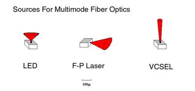
The most important component affecting loss
in a multimode cable plant is the source coupling light
into the fiber. Light sources may be LEDs or lasers.
Lasers may be VCSELs (vertical cavity surface-emitting
lasers) or Fabry-Perot lasers (telecom style.) Each of
these emits light in a different pattern (right), with
LEDs having the broadest beam, F-P lasers a very narrow
beam and VCSELs in between. The light coupled from the
source is transmitted in a multimode fiber in many rays or
modes, hence the name multimode. (below)
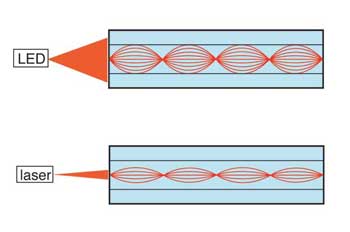
As you can see, a laser couples light only
into modes that travel near the center of the fiber while
a LED couples light into practically all the modes. Look
closely and you can see the modes near the center of the
fiber core (lower-order modes) travel shorter paths than
the modes near the edges of the core (higher order modes.)
The shorter path of the lower-order modes means that they
travel through less glass and suffer less loss than the
ones traveling in the outside of the core. That means a
laser suffers less attenuation (loss per unit length, in
dB/km) in the same multimode fiber than a LED.
Furthermore, as light travels down the
fiber, the attenuation changes. The light in the outside
modes is attenuated, leaving mostly light in the modes
near the center. At a kilometer from a LED source, the
light in the outer modes is mostly attenuated and the
light carried in the fiber looks more like the light
launched from a laser. This means the attenuation at that
point is less than at the beginning because its only in
lower order modes.
So what is the loss of the fiber? The
manufacturers spec for fiber is around 3 dB/km at 850 nm
and 1 dB/km at 1300 nm. That is for a test using a
calibrated source that is much closer to the launch of a
laser source than a LED. The difference in the attenuation
coefficient of a fiber tested with a laser or LED can be
1-2 dB/km. With a LED source, the first hundred meters of
fiber representative of a premises network may have an
attenuation of over 4 dB/km.
The same factors hold for connector and
spice loss. Most of the loss in connectors is due to
misalignment of the two fibers and the higher order modes
are much more likely to be lost at a connector than lower
order modes. A connector coupled to a LED source with a
short cable could have a loss of 0.5 dB while if it were
coupled to a laser source or were 1 km away could have a
loss of 0.3 dB.
By now, I suspect your head is swimming. If
you still have your wits about you, you may want to know
how any standards body can solve this issue. The answer is
how everything is solved compromise. Create a standard
launch condition that is more than a laser but less than a
LED, which today is appropriate, since its more like the
VCSELs (vertical cavity surface-emitting lasers) used in
todays Gigabit and faster multimode links.
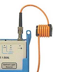
Manufacturers use special lensed sources in
their labs that can control the launch conditions exactly.
The way to approximate this launch for field testing is to
use a LED source and a mode modifier, usually a few turns
of the reference launch cable wrapped around a cylindrical
mandrel that filters out the higher order modes. The
mandrel size must chosen according to the fiber and cable
type being used.(right, Table below) These devices are
available from many test equipment manufacturers.
Its highly recommended that you use this
standard source method, as it will produce more consistent
test results and provide greater reproducibility better if
you ever have to retest. And the losses measured are going
to be lower so you are less likely to fail good cables.
Even so, the uncertainty of the measurement
is likely to be several tenths of a dB. The uncertainty
comes from the coupling of your reference cables to the
fiber under test, which includes the quality of the
terminations on the reference cables, how clean they are
and how many times they have been used, since they degrade
with use.
Below
is the mandrel wrap specification from TIA 568, which is
to be used with what is basically an overfilled
(Category 1 CPR) LED source.
TIA-568
Specified Mandrel Size
(Wrap launch reference cable five turns over the
specified size mandrel)
|
| Fiber
Type |
3mm
Jacketed Cable |
2.0
or 2.4mm Jacketed Cable
|
1.6mm
Jacketed Cable |
900
micron Buffered Fiber |
| 50/125 |
22
mm
|
23
mm |
24
mm |
25
mm |
| 62.5/125 |
17
mm |
18
mm |
19
mm |
20
mm |
NOTE
The mandrel
diameters are based on nominal values of 20 mm (0.79
in) and 25 mm (0.98 in)) reduced by the cable diameter
and rounded up.
Here are two other more technical articles on modal
distribution and control in MM fiber for testing.
Modal Effects
on Multimode Fiber Loss Measurements
Encircled Flux
For Multimode Fiber Measurements
So Why Arent OTDRs Used?
Some people think everybody uses
OTDRs for all fiber optic testing, but thats only true
for outside plant (OSP) applications. Most OSP
installations involve splicing singlemode fiber to get
longer runs and the OTDR allows verifying the quality of
the splice. But when that link is finished, it must still
be tested for insertion loss with a light source, power
meter and reference cables, just like premises cables.
Premises cables rarely have splices and are short, often
too short for the OTDR to measure.
Insertion loss and OTDR testing use
different methods. Insertion loss tests just like the
fiber will be used, with a source on one end and a
detector on the other, so tested insertion loss should be
close to what the communications link actually will see.
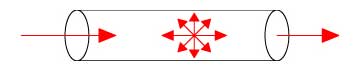
OTDRs, however, make an indirect measurement, based on
fiber scattering, the major source of loss of a fiber. It
sends a very powerful pulse down the fiber and some of the
scattering comes back toward the instrument, where it is
measured and stored. As the test pulse moves down the
fiber (right), it takes a snapshot of the fiber
illuminated by the test pulse from which information about
the fiber may be implied.
Everything the OTDR learns about the fiber
is dependent on the amount of light scattered back toward
it and how the instrument is set up for the test. This
backscatter is a function of the materials in the fiber
and the diameter of the core. Joints between two
dissimilar fibers that have different backscatter
coefficients will not allow one way measurements. One way
the loss is too high, the other way too low (maybe even a
gainer where the change in backscatter is more than the
loss of the connection.)
The second problem with OTDRs on multimode
fiber is the laser source. As mentioned above, lasers
couple light narrowly into multimode fiber and will
measure lower attenuation and connector or splice loss
than recommended by standards on the outward bound test
pulse, but scattered light probably overfills the fiber,
even more than a LED on the return. To date, we are
unaware of anyone who has modeled this and can provide
guidance on the expected test results from an OTDR.
In addition, there are problems in premises
applications with OTDR distance resolution. Light travels
about 1 meter in 5 nanoseconds. The width of the test
pulse is usually 10-30 ns and the minimum resolution of
the OTDR is about 3 times that or 2-6 meters. Highly
reflective events like multimode connectors in premises
cabling, cause instrument overload and lengthen the
minimum resolution of the instrument. Only a few
specialized OTDRs have the resolution needed for premises
cabling.
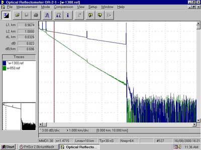
OTDRs are complicated instruments. Before
the OTDR is used to make a measurement, you have to set
all these parameters correctly: range, wavelength, pulse
width, number of averages, index of refraction of the
fiber and the measurement method (usually 2 types for each
measurement.) OTDR manufacturers should teach you how to
set up the OTDR properly and how to interpret the rather
complicated display. (left). But few customers are willing
to invest the day or two necessary to learn how to use the
instrument properly. So manufacturers create an autotest
function like a Cat 6 certifier that tests the fiber and
gives you a pass/fail result. Every debacle I have seen in
OTDR testing resulted from inadequately trained personnel
using autotest.
Unfortunately, because of their
indirect measurement technique, OTDRs do not easily
correlate with insertion loss tests, and thats why they
are not allowed by industry standards to be use alone.
Some users claim to have been able to control modal power
in multimode fiber and get correlation between OTDRs and
insertion loss tests, but results are hard to duplicate.
The FOA did a comprehensive comparison test ourselves
using special mode conditioners and were unable to get
correlation. In fact, some of our tests gave divergent
results between two different OTDRs!
If one considers the OTDR test to be a
qualitative not quantitative test, and one knows how
to interpret the OTDR trace properly, one can determine if
connectors and splices are properly installed and if any
damage has been done to the cable during installation. If
the user does not have the experience and knowledge to do
a proper analysis, the device usually only causes
problems.
Testing Efficiently And
Accurately
The contractor and the user
should agree on what documentation and testing are
required before the project is started. That documentation
should include the layout of the cabling, types and
numbers of fiber in each cable, connection diagrams and
insertion loss test results. That agreement should be part
of the bid and the contract. If the customer wants OTDR
data, they should be quizzed on why they want it and be
made to understood that OTDR testing is time consuming and
expensive (like the instrument itself!)
Before beginning the installation, the
contractor should calculate a loss
budget for each link based on the length of the link
and the number of connections. This confirms the equipment
will operate over that link. Then the expected loss will
be known to allow a pass/fail decision by the person doing
the testing. The contractor should have the proper test
equipment and installers using the equipment should be
familiar with its use.
When terminating cables, each cable should
be tested with a source and power meter using high quality
reference cables. The accuracy of the measurements depends
on having properly operating test equipment, high quality
reference cables with a mandrel wrap, cleaning all
connections before every measurement and using a
consistent measurement technique.
Reference cables should be tested with the
same test equipment they are used with each day and
cleaned carefully before each measurement. This also
provides good practice to the installers using the
equipment. All installers using the test equipment should
be familiar with using the mandrel wrap on the launch
cables.
Since the light source and power meter
insertion loss test requires an instrument at each end of
the cable, two installers working together will speed up
the process. A visual tracer can be used to identify the
next fiber to test, making communication easier and
cheaper than using cell phones.
Data should be recorded in a spreadsheet
alongside the loss budget calculation used for pass/fail
criteria so the contractor and customer can verify the
installation. Troubleshoot high loss links that fail
testing by testing single ended with only a launch
cable. Bad connections will show up as high loss when
connected to the launch cable but not when connected
directly to a power meter so reversing the cable test
direction will usually find bad connectors.
Return to the FOA Online
Fiber Optic Reference Guide Table of Contents
|
