Testing
The Installed Fiber Optic Cable Plant - 5 Standard Ways
Abstract:
We often are asked questions about testing installed
fiber optic cables that indicate the industry standards
are confusing, have little information on measurement
accuracy and no guidelines for troubleshooting. This web
page is an attempt to clear up some of this confusion.
But remember, as Bob Metcalfe, co-inventor of Ethernet,
says, "Standards are wonderful, because we have so many
to choose from!"
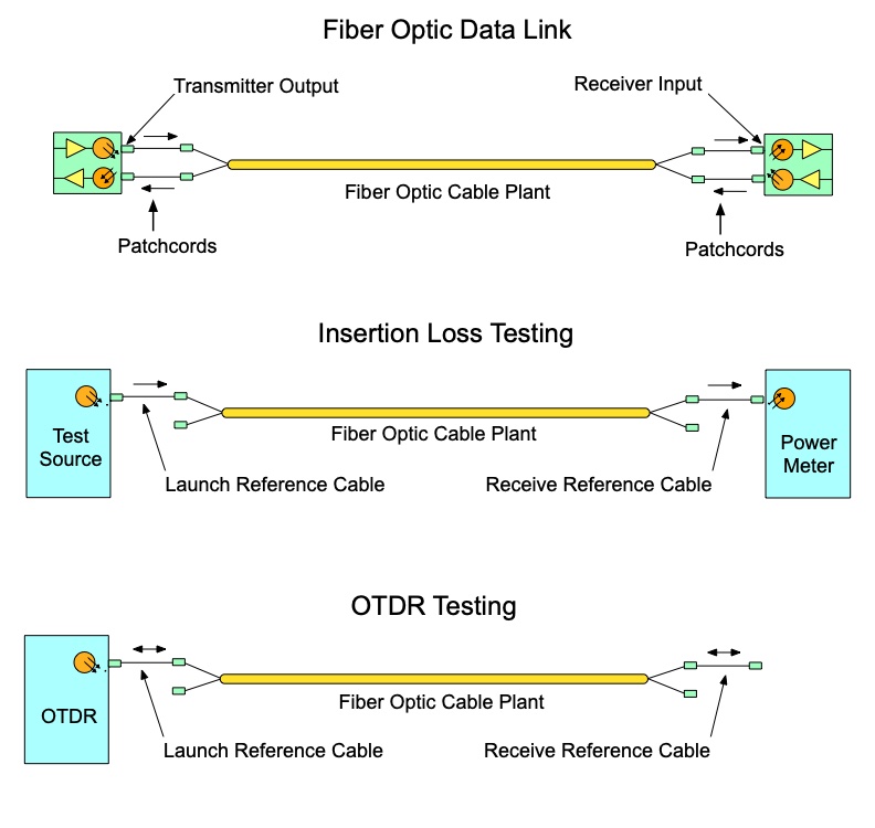
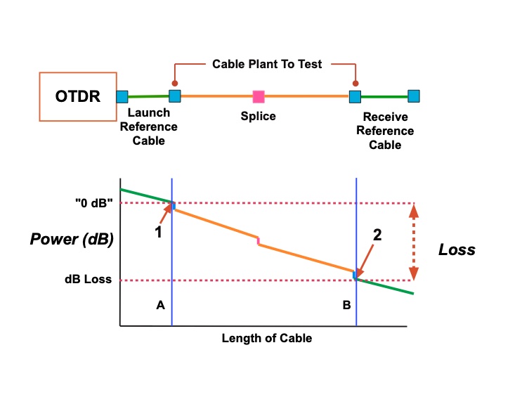
Testing Fiber Optic Cables
In order to test
the fibers in a fiber optic cable with a power meter and source or with an OTDR, one
needs to
establish test conditions. The test
conditions should be similar to how the actual cable plant will be used
when communications equipment is connected (see drawing below.) For
insertion loss
testing, this requires reference launch
jumper
cables to connect the test source to the
fiber in the cable under
test and receive cables to connect the fiber
optic
power meter. For OTDR testing, this requires
a reference launch cable to connect the OTDR to the fiber in the cable
under test and a receive cable at the far end of the fiber.
6 Ways? It has
been said occasionally that there are in fact 6 ways -
if you include single-ended
testing used for patchcords. That's true, and this
method is used to troubleshoot bad connectors on cables
by testing each end separately, but the loss of a cable
plant must be done "double ended" as described here.
Standards Update: The old
TIA OFSTP-14 was replaced by a new ISO standard. The TIA
has adopted IEC 61280-4-1 as the replacement of
OFSTP-14. Most of the two documents is the same, with
some important exceptions.
• For insertion
loss, three reference methods are are still approved,
but the nomenclature is different - no more confusing "Method A, B
or C" designations- it's now 1, 2 or 3 reference cables.
• OTDR testing is
now an approved second tier test method as long as you
use both launch and receive cables.
• Reference test
cables with "reference grade connectors" are
recommended.
• Methods are given
for testing and verifying the loss of reference test
cables.
• For multimode
modal control, CPR with a mandrel wrap is gone, at least
for 50/125 fiber at 850nm, replaced by "Encircled
Flux," a complex
method of measuring the source output, but the
old mandrel wrap is a close approximation of EF launch conditions.
Most of the other changes are nomenclature. In the meantime,
continue testing as usual.
There are five ways listed in various
international standards from the EIA/TIA and ISO/IEC to
test installed fiber optic cable plants. Three of these methods use test
sources and power meters to make the measurement (called insertion loss testing), while
the fourth and fifth use an OTDR. The best way to
understand them is to look at the diagrams above and below.
The source/power meter method, generally
called "insertion loss," approximates the way the actual
network uses the cable plant, so one would expect the loss
to be similar to the actual loss seen by the network,
which is preferable. The OTDR is an indirect method, using
backscattered light to imply the loss in the cable plant,
which can have large deviations from insertion loss tests.
OTDRs are more often used to verify splice loss or find
damage to cables.
The differences in the three insertion loss
tests are in how we define the "0 dB" reference or no loss. All three
tests end up with the same test setup (Figure 1), but the
reference power can be set with one, two or three cables
as shown in the three setups below. The different methods of setting the 0 dB reference are needed because of the variety of fiber optic connectors on cables and test equipment.
All test methods have measurement uncertainty.
After we explain the methodology, we will examine the
measurement uncertainty.
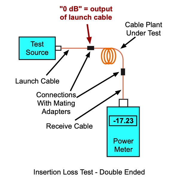
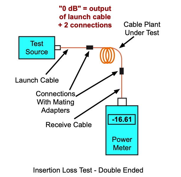
Insertion Loss - Double-Ended Cable Test
Per TIA
OFSTP-14 (Multimode) and OFSTP-7 (Singlemode)
(and similar international standards)
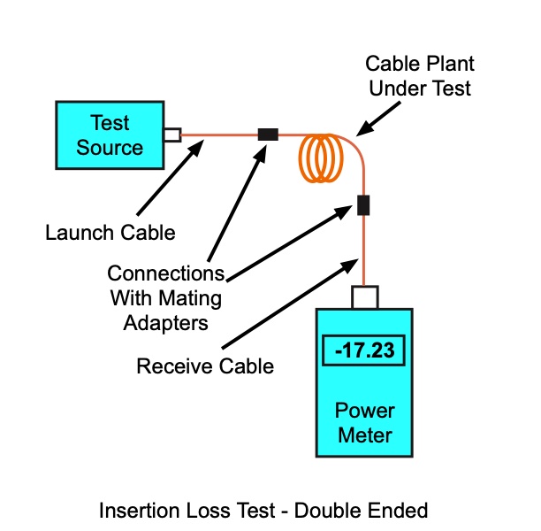
Insertion loss testing with a test source and power meter
simulates the way the cable plant will be used with an
actual link. The test source mimics the transmitter, the
power meter the receiver. But insertion loss testing
requires reference cables attached to the source and meter
to connect to the cable under test.
The insertion loss
test can use 1, 2 or 3 reference cables to set the “zero
dB loss” reference for testing. Each way of setting the
reference gives a different loss when testing the same cable plant.
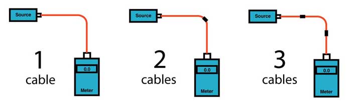
Why 3 Ways?
The
reason for the existence of three methods is the
compatibility of test equipment to the cable plant;
whether the test equipment has connector interfaces that
allow direct connection to the cable under test.
The
options for use of these three methods are:
- If
the test equipment has connectors
compatible with the cable plant, a one-cable
method can be used. This is usually the preferred method.
- If
the test equipment does not have
connectors compatible with the cable
plant, a two- or three-cable method must
be used.
- If
the test equipment does not have
connectors compatible with the cable
plant and the connectors are the “plug and
jack” or “male, female” type, a
three-cable method must be used.
It all depends on the connectors on the cable plant you
are testing and the connector interfaces on your test
equipment.
Why use a 1-cable method?
The 1-cable method is used when the instruments have connectors that match the cable plant under test, e.g., both have SC connectors. The 1-cable method has always been the method of choice
because it does not require compensating for the
connections in the reference cables when setting the
"0dB" reference. It's like we discussed measuring
transmitter power above. You measure the output of the
launch reference cable, connect it to the cable plant
under test, launch power through that first connection
and measure the loss of all losses in the cable plant.
The meter connects to the cable plant at the far end
with a receive reference cable, and when the meter makes
it's measurement it includes the connection of the
receive reference cable. Thus both connections on each
end of the cable plant are measured, Just like the
actual link will work in operation. No corrections are
needed. (This method was originally called "Method B" in TIA standards.)
Why use a 2-cable method?
If you have a LC cable plant and your
instruments have SC connector interfaces? You
can use hybrid reference cables
with SC connections on one end for your
instruments and LCs on the other end to mate with the cable plant.
Use a LC mating adapter to set your 0 dB
reference -
including that connection - and make
measurements
remembering - or ignoring - that your reference
value
included one unknown connection. (This method was originally called "Method A" in TIA standards.)
Why use a 3-cable method?
If you are trying to test connectors that do not
match the connections on your instruments nor do they
mate with each other because they are gendered -
male/female or plug/jack? Hybrid reference cables won't
help here, so you go to a "cable substitution" test. Set
up your instruments with hybrid cables and set your
reference with a third cable that is a short version of
the cable plant you want to test. Since most cable
plants using plug/jack connectors (like a MPO prefab
cable plant or multipin military connectors) have the
permanently installed cable plant end in connectors of
the same gender (MPO jacks are connectors with pins),
you will have your instruments with similar cables and
the reference cable will have the opposite styles of
connectors to mate with them. (This method was originally called "Method C" in TIA standards.)
Just remember that you will make measurements that yield
different loss values depending on the reference method
you use.
All
three methods are approved in most standards and at
least the 1-cable or 3-cable methods are approved in all
standards we're aware of.
Generally
network standards prefer the 1 reference cable loss
method, but that requires that the test equipment uses the
same fiber optic connector types as the cables under test.
If the cable has different connectors than the test
equipment (e.g. LCs on the cable and SCs on the tester),
it may be necessary to use a 2 or 3 cable reference, which
will give a lower loss since connector loss is included in
the reference and will be subtracted from the total loss
measurement. Any of the three methods are acceptable, as
long as the method is documented. Be careful, however, as
most network link losses may assume a 1 cable reference,
which can affect the acceptance of the cable plant.
It is important to understand that the three reference
methods will give different loss readings because of the
connections included when setting the reference with 2 or
3 cables. Here is
an explanation of the differences in loss readings you
will see with each method.
Insertion Loss, 1 Cable Reference
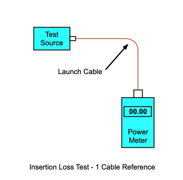
This method uses only one reference cable attached between
the test source and the power meter. The meter, which has
a large area detector that measures all the light coming
out of the fiber, effectively has no loss, and therefore
measures the total light coming out of the launch
reference cable. Once the reference is set, the launch
reference cable should not be removed from the source, as
it may have a different coupled power when reattached.
When the cable is tested as shown above, the
loss measured will include the loss of the reference cable
connection to the cable plant under test, the loss of the
fiber and all the connections and splices in the cable
plant and the loss of the connection to the reference
cable attached to the meter.
It is important to note with all these tests
the quality of the reference cables is important in the
uncertainty of the measurement. If one uses reference
cables with bad connectors, the losses when mated to the
cable under test will be higher than they should be, not a
good result if you want the installed cable to show the
quality of your installation processes! Installers should
test all reference cables using FOTP-171 single-ended
cable tests to ensure their quality. Cables with losses
higher than 0.5 dB per end should be cleaned and retested,
then discarded if they do not meet the 0.5 dB max loss.
Dirt is always another issue. If any of
the connectors are dirty, measurements will show higher
loss and more variability.
Insertion Loss, 2 Cable Reference
 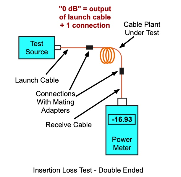
This method probably evolved from the telcos
where lengths were long and the instruments were brought
together only once a day for calibration, plus instruments
often had connectors different from the cable plant (e.g.
biconics on the cable plant and SMAs on the instruments.)
Here the launch reference cable is attached to the source,
the receive reference cable to the meter, then the two
cables are mated to set the reference. Once the reference
is set, the launch reference cable should not be removed
from the source, as it may have a different coupled power
when reattached, and one should probably do the same at
the meter.
Setting the reference this way includes one
connection loss (the mating of the two reference
cables)
in the reference value. When one separates the
reference
cables and attaches them to the cable under test,
the dB
loss measured will be less by the connection loss
included
in the reference setting step (compare the display
on this meter to the one above used with a 1 cable reference.) That's
approximate, by the
way, since the variations in mating alignment make
the
loss slightly different each time two connectors
are
mated.
Anyway, this method gives a loss that's
less than the 1 cable reference, Method B (above) and
because one connection is included in settting the
reference, it has a higher variability. Dirt is always an
issue. If any of the connectors are dirty, measurements
will show higher loss and more variability. If the
connectors are dirty when setting the reference but
cleaned afterwards before testing the cable, one gets a
lower loss, or sometimes even a gain!
Why would you use this method? If your
test equipment has different connectors than the
cable
under test, but the connectors are all mateable
with
proper mating adapters, this method can be used. A
standard example is test equipment with SC connectors and a cable plant
with LC connectors. The reference cables would be hybrids with SC
connectors on one end to mate with the equipment and LCs on the other
end to mate with the cable plant.
Insertion Loss, 3 Cable Reference
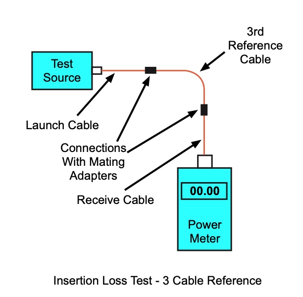 
Some of the newer connectors are
male/female or plug/jack, not two males that use a mating
adapter to create a connection. One connector is used on
the jack in the wall or patch panel and one is used on a
patchcord. Examples are the MPO and mil-style 38999. These
connectors cannot be mated to test equipment nor can two
similar ( plug or jack ) be mated with a mating adapter.
Reference cables generally will be patchcords with
plugs while the cable under test will have jacks on either
end. The only way to get a valid reference is to use a
short cable of known good condition as a "stand-in" for
the cable to be tested (often called a "golden reference cable") to set the reference. To test a
cable, replace the reference cable with the cable to test
and make a relative measurement. That means this is sometimes referred to as a "cable substitution test."
Obviously this method includes two
connection losses in setting the reference, so the
measured loss will be less by the two connection losses
and have greater uncertainty (compare the display on this meter to the one above used with a 1 cable reference.) . Dirt is again an issue. If
any of the connectors are dirty, measurements will show
higher loss and more variability. If the connectors are
dirty when setting the reference but cleaned afterwards
before testing the cable, one gets a lower loss, or even a
gain!
Why would you use this method? If your
test equipment has different connectors than the
cable
under test and the connectors on the cable to test
are not
mateable, this method can be used. For example a
cable plant with MPO connectors has two types of connectors, those with
pins and those with holes, so when the cables mate, the pins go into the
holes on the other connector to align the connectors. The installed
cable plant has connectors with pins while patchcords have connectors
with holes. In setting the reference, the reference cables would have
connectors with holes while the 3rd reference cable would have
connectors with pins. When that cable is used for a reference then
removed, the reference cables can be mated with the ends of the
installed cable plant which has connectors with pins.
Since this method works
with any connector style, it has been chosen for several
international test standards.
Since there is some confusion about what each method
actually measures, the FOA has a web page that explains it
in simple diagrams and math. Read
Loss Math.
Summary: Which Reference Method Should
Be Used?
For insertion loss testing, it depends
on the types of connectors on your test equipment and the
connectors on the cables you need to test. If your cable
plant has the same connector styles as your test set, or
all the connectors use the same 2.5 mm ferrule style
common to ST, SC, FC and some other connectors, you can
use the one cable reference method.
If your test equipment has ST or SC
connectors and you must test LCs on the cable plant, you
may have no choice but to use a 2-cable reference or 3
cable reference. To compare these test results with
a 1 Cable Reference, you must add an estimated loss
for the connector included in the reference measurement,
say 0.3-0.5 dB for a typical connector on a high-quality
factory-made patchcord.
If your test equipment has ST or SC
connectors and you must test duplex male/female connectors
like the MT-RJ on the cable plant, you may have no choice
but to use a 3-cable reference. To compare these test
results with a 1 Cable Reference, you must add an
estimated loss for the connectors included in the
reference measurement, say two times 0.75 dB for a typical
MT-RJ connector on a high-quality factory-made patchcord.
More on testing cables
with different types of connectors.
Table 1. Reference methods for fiber optic insertion loss testing.
| Reference
Method (OFSTP-14) |
Reference
Cables |
Connectors
Included in Reference Measurement |
Estimated
reduction in measured loss |
Estimated
increase in errors |
| 1
Cable Reference | 1,
launch | 0 | 0
dB | 0
dB |
| 2 Cable
Reference |
2,
launch and receive |
1 |
0.2-0.75
dB |
+/-0.2
dB |
| 3 Cable
Reference |
3,
launch, receive and “golden cable” |
2 |
0.4-1.5
dB |
+/-0.25
dB |
Table 2. Recommended reference methods for connectors
| Connector
Type |
Mates
to test equipment |
Does
not mate to test equipment |
| Plug
to Plug with mating adapter |
1,
2 or 3 Cable Reference |
2 or 3 Cable Reference* |
| Plug
to Jack |
1
or 3 Cable Reference |
3
Cable Reference |
*The 2 Cable Reference can be used if the connector
under test can be adapted to the connector interface on
the test set – e.g. a tester with SC interface, but ST and
FC can be mated to SC with a hybrid mating adapter, so SC
reference cables can be used.
Reference Cables For OTDR Testing
OTDRs test from one end of the
cable using the backscatter signature of the fiber
to make
an indirect measurement of the fiber. OTDRs always
require
a launch cable longer than the OTDR "dead zone" to
allow the instrument to settle down after
reflections from the high powered test pulse
overloads the
instrument. OTDRs have traditionally been used
with long
distance networks where often only a launch cable
is used because the test is mainly to verify splices as they are made.
However, this method does not measure the loss of the connector on
the far end. Adding a cable at the far end allows
measuring the loss of the entire cable, but negates the
big advantage of the OTDR, that it makes measurements from
only one end of the cable, since a tech is required to
attach the receive cable to each fiber as it is being
tested. More
on OTDR testing.
OTDR Test With Launch
Cable Only
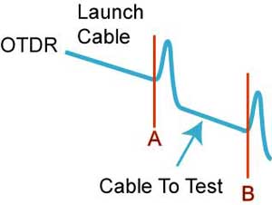
When testing with an OTDR using only
the launch cable, the trace will show the launch cable,
the connection to the cable under test with a peak from
the reflectance from the connection, the fiber in the
cable under test and likely a reflection from the far end
if it is terminated or cleaved. Most terminations will
show reflectance that helps identify the ends of the
cable.
Using markers A (set at the end of the
launch cable) and B (set at the end of the cable under
test) , the OTDR can measure the length of the cable under
test and the loss of the connection to the cable under
test plus the loss of the fiber in the cable under test
and any other connections or splices in the cable under
test (not shown.)
This method does not, however, test the
connector on the far end of the cable under test because
it it not connected to another connector, and connection
to a reference connector is necessary to make a connection
loss measurement.
OTDR Test With Launch And
Receive Cable
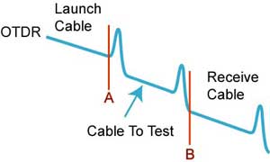
If a receive cable is used on the far
end of the cable under test, the OTDR can measure the loss
of both connectors on the cable under test as well as the
fiber in the cable and any other connections or
splices in the cable under test (not shown.) The
placement of the B marker after the connection to the
receive cable means some of the fiber in the receive cable
will be included in the loss measured. Most OTDRs have a
"least squares" test method that can subtract out the
cable included in the measurement of a single connector,
but this will not work on a double ended cable loss test.
Different Results From
Different Reference And Test Methods
So just how much does the loss of a
cable plant change with the different methods? The table
below shows test results for a 520 meter simulated cable
plant with multimode fiber tested four ways
at 850 nm using several different sets of reference cables
to see the results. Unfortunately, we did not use a
receive cable to get data for the fifth method mentioned
above, but we did take data in both directions. Using 10
different sets of reference cables and making multiple
measurements allowed calculating an average of each
measurement, comparable to what several different test
crews might find, plus calculating the standard deviation,
a statistical indication of the repeatability of the
measurement.
-
| Test
Method |
Results,
Loss in dB, Standard Deviation |
| 1
Cable Reference |
2.96
dB, +/-0.02 dB |
| 2
Cable Reference |
2.66
dB, +/-0.20 dB |
| 3
Cable Reference |
2.48
dB, +/-0.24 dB |
| OTDR
Launch Cable Only |
1.91
dB / 2.05 dB (reverse directions) |
|
-
Note how the loss of our test cable plant reflects the
comments we made above. The one cable reference method has
higher loss than the other methods, but it also has much
less measurement uncertainty (standard deviation.) The 2
and 3 cable reference methods have less loss because we
have subtracted the connector loss(es) included when we
set the reference for 0 dB loss, and the uncertainty is
higher because of the greater variance when connected to
the reference cables. And the OTDR measurement is
significantly lower than the other three methods plus is
0.14 dB different according to which direction we are
testing in. Note that if we added to the OTDR loss the
average connector loss difference in the other tests,
about 0.25 dB, the loss would still only be about 2.1 -
2.2 dB, significantly less than any of the insertion loss
tests.
If you want to read more about what each insertion loss
method actually measures and why the uncertainty is
different for each method, the FOA has a web page that
explains it in simple diagrams and math. Read
Loss Math.
Interpreting Test Data
What is the loss of this cable plant?
Well all of these measurements are strictly according
to international standards, so you can take your choice!
However, it might cause a problem if you attach some
network electronics.
Most network power budget specifications have been
written around an insertion loss test that uses a one cable reference
method. If your
cable has been tested with any other method, the lower
loss you measure will give you a false measurement of
system margin. If you are dealing with new, fast networks
like Gigabit Ethernet or Fibre Channel which have much
smaller operating power margins, you could be in trouble.
The different loss obtained in OTDR
measurements comes from it’s completely different
methodology. OTDRs use backscattered light to imply the
measurement while insertion loss is measured directly by
transmission. Some claims for using mode
conditioners to make OTDR and insertion loss data
correlate has not proven reproducible in independent tests
conducted by the FOA (Read
the report here.) A single-ended OTDR measurement,
which most tech use, does not test the connector on the
far end. Recent standards mention and sometimes require a
receive cable for OTDR tests, which would have added
0.2-0.3 dB to the loss measured in the test detailed
above. But having to use a receive cable with an OTDR
negates its advantage of being able to be tested from one
end by a single technician.
Additional Reading
Testing cables with
different types of connectors.
Fiber Optic
Measurement Accuracy
Table of Contents: The FOA
Reference Guide To Fiber Optics
|
