
|
Patchcord And Connectorized Cable Testing After connectors are added to a cable, testing must include the loss of the fiber in the cable plus the loss of the connectors.On very short cable assemblies (up to 10 meters long), the loss of the connectors will be the only relevant loss, while fiber will contribute to the overall losses in longer cable assemblies. In an installed cable plant, one must test the entire cable from end to end, including every component in it, such as splices, couplers, and connectors intermediate patch panels. Obviously one cannot test cable assemblies in the same manner as fiber connectors alone (FOTP-34), since those tests are destructive. Instead of using a cutback test, one uses a source with a launch cable attached to calibrate the power being launched into the cable under test. This method was not used at first; a cable substitution test was used. (A cable substitution test is still used for connectors that are not designed to be mated to like connectors, such as some POF connectors.) In this method, one attaches a reference cable of short length (about 1 m) and high quality to the source and records the power. After removing this cable from the source, the cable to be tested is then attached to the source and the power measured. The loss of the cable is them referenced to the loss of the first cable. This method was abandoned, since it often lead to confusion when the cable under test was better than the reference cable and had a "gain" not a loss, the coupling to the source was highly unrepeatable, and the test did not adequately test the centering geometry of the fiber in the ferrule of the connector. 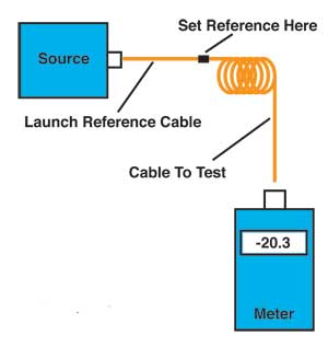 A better test, FOTP-171 was developed along the lines of FOTP-34 for connectors, covered in FOA Standard FOA-2. One begins by attaching a launch cable to the source made from the same size fiber and connector type as the cables to be tested. The power from the end of this "launch cable" is measured by a power meter to calibrate the launch power for the test . Then the cable to test is attached and power measured at the end again. One can calculate the loss incurred in the connectors mating to the launch cable and in the fiber in the cable itself. Since this only measures the loss in the connector mated to the launch cable, one can add a second cable at the power meter end, called a receive cable , so the cable to test is between the launch and receive cables. Then one measures the loss at both connectors and in everything in between. This is commonly called a "double-ended" loss test and is identical to the test for installed cable plants used in FOA-1 and OFSTP-14 or OFSTP-7 for singlemode. Note: FOTP-171 includes dozens of test methods that cover all types of test situations, different modal conditioning, types of connectors, hybrid cables, etc. but all are variations of the test shown here. OTDRs are not recommended for cable loss testing as the test method is subject to too many potential errors. If the cable is long enough, the OTDR can be used for reflectance testing (see below.) See the OTDR section for information on how OTDRs work and their measurement uncertainty. Finding Bad Connectors Since single-ended testing only tests the connector attached to the reference cable, it is a powerful test for determining which connector is bad on a terminated cable. If a test shows a jumper cable to have high loss, there are several ways to find the problem, starting with visual inspection. If you have a microscope, inspect the connectors for obvious defects like scratches, cracks or surface contamination. If they look OK, clean them before retesting. Retest the launch cable to make certain it is good. Then retest the jumper cable with the single-ended method, using only a launch cable. Test the cable in both directions. The cable should have higher loss when tested with the bad connector attached to the launch cable, since the large area detector of the power meter will not be affected as much by the typical loss factors of connectors. Mode Power Distribution Effects on Loss in Multimode Fiber Cables The biggest factor in the uncertainty of multimode cable loss tests is the mode power distribution caused by the test source. Read more about mode power distribution. Choosing a Launch Cable for Testing Obviously, the quality of the launch cable will affect measurements of loss in cables assemblies tested against it. Good connectors with proper polish are obviously needed, but can one improve measurements by specifying tight specifications on the fiber and connectors? If the fiber is closer to nominal specifications and the connector ferrule is tightly toleranced, one should expect more repeatable measurements. However, it seems that the large number of factors involved in mating losses makes controlling these tolerances impossible. Therefore, it is recommended that launch cables be chosen for low loss, but not specified with tighter tolerances in the fiber or connector characteristics. It is probably much more important to carefully handle the test cables and inspect the end surfaces of the ferrules for dirt and scratches regularly. Optical Return Loss (Reflectance) Testing of Cable Assemblies Testing the optical return loss of cables and cable assemblies is very important for singlemode laser systems, since light reflected back into the laser may cause instability, noise or nonlinearity. While testing the ORL of a cable assembly is similar to that of a connector, using either FOTP-107 or the OTDR method, several factors should be noted to minimize errors. First, be certain that the launch connector is of the finest quality obtainable, and inspect it often for dirt, contamination and scratching. Repolishing is possible for most keyed, ceramic ferrule connectors and will often improve measurements. Also insure the splice bushing used is kept clean and does not show wear. Remember to terminate the connector on the far end of the cable assembly, otherwise it will reflect light and give false readings. Dipping the connector into index matching fluid or gel will usually do, but putting several tight turns in the fiber to create attenuation will also minimize the reflection effects. OTDRs are limited in their usefulness in testing reflectance of jumper cables, since the jumpers are often too short for the resolution of the OTDR. If using an OTDR, make certain that the OTDR reflectance spike does not exceed the dynamic range of the OTDR (the reflectance peak will be flat-topped), or the measurement will underestimate the reflection. FOA Standard FOA-2 Recommended reading: 5 Ways to test a fiber optic cable, 3 different ways to set a "0 dB" reference Testing cables with different types of connectors Accurately Testing Fiber Optic Cables The Math of Insertion Loss Testing - Reference Methods More on OLTS/OTDR testing. More on optical return loss is on the page about connector testing. Videos on cable testing on the FOA Channel on  |
|
|