Optical LANs
Introduction
Centralized
Cabling - Fiber to the Desk and Fiber To The Office
Passive Optical LANs
Designing
And Installing Optical LANs (OLANs)
Testing
OLANs
Understanding
Passive Optical LANs
Passive optical
LANs (POLs or passive OLANs) use standard
FTTH (fiber to the home) passive optical network (PON)
architecture and protocols which are quite different
from typical LANs. In a Ethernet LAN with structured
cabling architecture, Ethernet switches in the main
equipment room connect to routers for Internet connections
and servers in the corporate data center to provide data
for users. Users are connected on a multi-link system that
uses backbone cabling to connect the main switches to
local switches in the telecom rooms near the users. Users
will then be connected over horizontal cabling, usually
UTP which runs from the telecom room to the work area or
cabling to wireless access points. The telecom room
requires uninterruptible, data-quality power, special data
grounding and usually air conditioning to keep the
temperature in the telecom room under control.
Passive optical
LANs use a different architecture than LANs with
electronic switches. Passive optical LANs use optical
splitters to divide the optical signal to allow up to 32
devices (ONTs) to be connected to one port on the optical
line terminal (OLT) that is the center of the LAN.
Downstream, the splitter splits the signals to all the
devices and upstream it combines them into one fiber,
allowing bidirectional signals on one singlemode fiber.
Each ONT is usually a multi-port gigabit Ethernet switch
in a LAN, but it can also be a switch for multiple phone
lines or even a FTTH triple play (phone/Internet/TV)
converter.
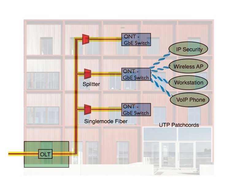
Passive optical
LANs use internationally
standardized systems called GPON (Gigabit PON) or
EPON (Ethernet PON) with GPON the most popular. A GPON
system diagram is shown below.

Diagram of a
typical POL. Signals are transmitted downstream at
1490nm and upstream at 1310nm. Downstream the splitter
"splits" the signal for up to 32 ONT connections on only
a single fiber each while upstream it "combines" the
signals from the 32 ONTs onto the single fiber
connecting the splitter to the OLT. (Click
here for a bigger version of the diagram)
A POL cable
plant needs nothing but passive components - fiber optic
cabling and a splitter - between the main equipment room
and the work area. Signals are transmitted
simultaneously in both directions at two different
wavelengths
on just one singlemode fiber using
wavelength-division multiplexing (WDM), so each work
area needs only a single singlemode fiber to connect to
the network. FTTH passive optical networks use fiber
optic splitters to split out a downstream signal to a
number of users, usually 32, reducing the complexity of
the electronics and the bulk of the cabling, plus it
spits the cost of the downstream electronics by the
number of users, making the cost per user much lower,
even lower than a link using copper cables between
Ethernet ports. Upstream, the POL uses the coupler as a
combiner - combining the incoming signals into a single
fiber to connect to the OLT. Each user work area has a
ONT that uses an inexpensive 1310nm laser for upstream
signals. In both directions the system will work with
~13-28dB loss and most of the loss will be in the
coupler. With a design specification of 10km links, POLs
offer maximum flexibility to users spread over a large
geographic area, not just a campus but large
manufacturing plants or even a small city.
When talking to
IT techs, we generally explain that the PON splitter
serves the same purpose as a switch but requires no
power/ground/AC and takes a fraction of the space.
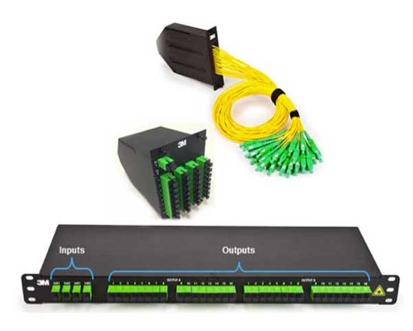
Typical
splitter packaging (3M)
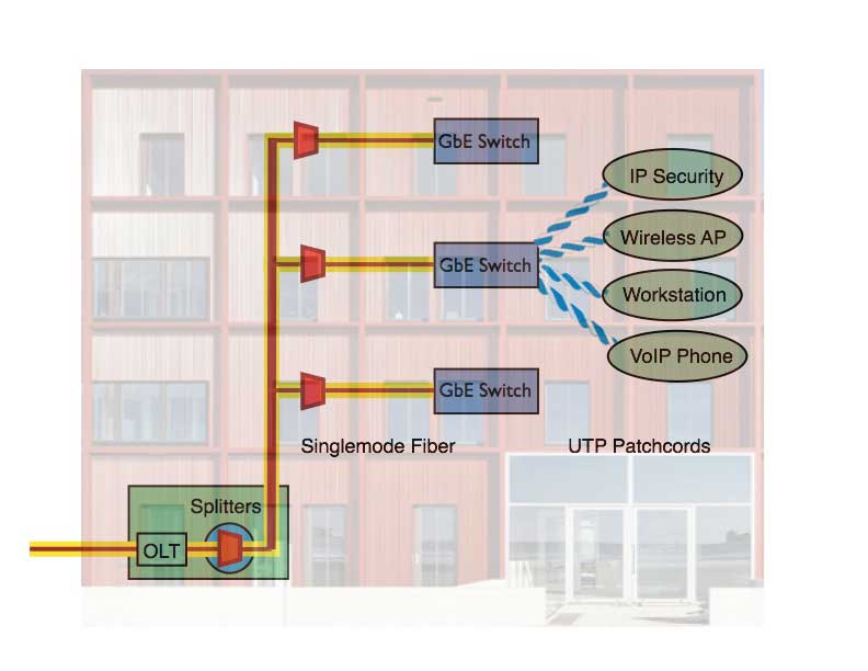
A block diagram
of a typical POL system. Splitters can be cascaded for
the 32X split ratio to split nearer work areas to reduce
cabling.
If we split the
downstream signal to 32 users, how does each user get
their specific data? The data is transmitted downstream
(at 2.5 Gb/s in GPON, currently the most popular FTTH
network used for POLs) using time division multiplexing
and - this is important - each user's data is
encrypted to prevent other users from intercepting
their data. The combination of fiber cabling and
encryption makes POLs highly desirable for those
concerned about security. The downstream multiplexing
can dynamically allocate bandwidth as needed. Upstream
signals in GPON are at 1.25 Gb/s.
10Gb/s GPON and
EPON (PONs that use Ethernet protocols) are available
that operate at different wavelengths so they can be
used on the same PON cable plant simultaneously. Thus a
GPON system can be built today using 2.5/1.25 Gb/s
equipment and upgraded to 10G in the future, even
leaving both systems for simultaneous use. Here
is more information on all PON standards.
ONTs in LANs
usually incorporate 4 to 24 gigabit Ethernet ports
(1000base-T over copper UTP patchcords) and often
include POE (power over Ethernet) for powering connected
devices. Other options are available. A triple-play ONT
from FTTH gives voice/data/video outputs. Multiple POTs
phone ports, more or less Ethernet ports, etc. are
available from various vendors. The ONT is powered
locally and can incorporate power over Ethernet (PoE) to
power local devices like WiFi access points, voice over
IP (VoIP) phones or video cameras. Having local PoE
provides the convenience of PoE without the high power
losses encountered in long horizontal cable runs.
Those
experienced in typical Ethernet LAN hardware and cabling
may have trouble believing the hardware simplicity of
POLs. The OLT that connects all the users also includes
connections for outside services (telco and Internet).
In fact, most OLTs are designed for one or more 10Gb/s
connections, hardly the typical slow T1-T3 or 10-50Mb/s
available through routers for most LANs. t.
POLs are particular well suited for large LANs. A small
rack mounted system can support 2000+ connections with
splitters which connects ~8000 users via 4-port switches
at the work area. Compare that to the room full of
Ethernet switches to support 8000 users! Even smaller
units are available to support fewer users. At the work
area, small switches about the size of a cable modem or
DSL modem are common, but switches that fit in a wall
outlet are also available. And, of course, cabling is
greatly simplified. with just a few singlemode fibers
needed to make large numbers of connections, compared to
large bundles of UTP copper cables.
Security And Reliability
POLs are adapted from telco systems that are designed for
99.999% reliability, at least 10X normal LAN components.
UPS power is required only at the main equipment room and
at the user work area if desired. No power is needed at
any intermediate point like traditional structured cabling
requires for switches in a telecom room. Redundancy can be
built into systems using splitters with two inputs instead
of one, with each input connected to a separate OLT for
backup.
As mentioned above, signals are encrypted downstream and
systems that encrypt upstream and monitor fibers to detect
tapping are available for high security areas.
Passive OLANs and Cabling
Standards
One question that often arises is how passive OLANs fit
into the usual structured cabling standards. These
networks are recognized by standards groups and in fact
are fairly simple variations of the usual cabling
architecture. Cabling standards have always recognized
singlemode fiber and now include splitters in the
standards.
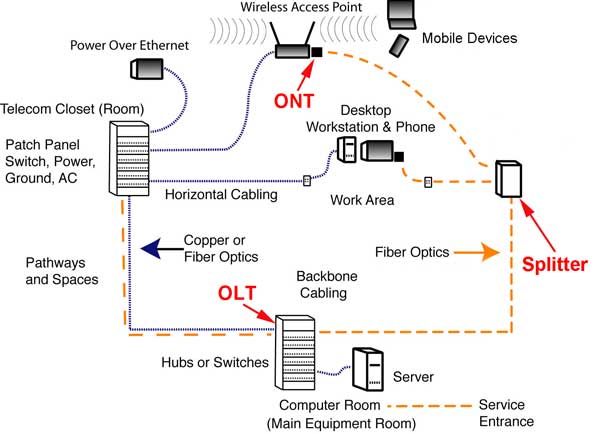
This is a basic diagram of structured cabling as defined
by TIA-568 or ISO/IEC 11801. A passive optical LAN based
on PON FTTH components simple adds a passive splitter to
the cable plant architecture (which can be considered
either centralized fiber or a singlemode fiber backbone)
where other networks would only have a patch panel.
Designing and Installing
OLANs
Most buildings designed in the last 20 years have been
designed around structured cabling with large areas set
aside for pathways and spaces, most of which are not
necessary for OLANs. Some OLAN users have actually
recovered spaces allocated for telecom rooms. Cable trays
emptied when obsolete UTP cables are removed for recycling
can be left since removing them is costly. Older buildings
that were designed before structured cabling standards
that have always been difficult to install cabling systems
are much easier, obviously.
Perhaps the best example of the savings in cabling bulk
when using an OLAN is this photo taken of the computer
room at the San Diego Central Library. Note how few cables
are visible - just a few ducts for fiber optic
cables. More
photos of the San Diego Library showing the total
installation before and after opening are here.

As we mentioned above, OLANs are using only singlemode
cables which are easy to install but require special
termination procedures (generally prepolished/splice
connections) or using prefab cable assemblies. Many of the
components are similar to those developed to ease installation
of FTTH (as shown here). Manufacturers have also
developed special hardware to simplify the prefab cable
plant installation like the module shown below.
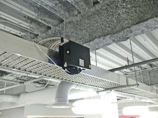
Prefab Cabling Module (TE Connectivity)
Testing POLs is easy for insertion loss but requires
special knowledge with OTDRs as they splitter can be
confusing. Cable plants with splitters have different
characteristics upstream and downstream so techs should be
trained on the special needs of POL testing with OTDRs. More
on testing PONs.
Training And
Certification
FOA has an Optical LAN (OLAN) specialist certification
(CFOS/L) with an online
self-study program at Fiber U and training available
from FOA approved schools.
More On OLANs
Introduction
Centralized
Cabling - Fiber to the Desk and Fiber To The Office
Passive Optical LANs
Designing
And Installing Optical LANs (OLANs)
Testing
OLANs
Training And
Certification
Fiber U has a free online self-study
program on optical LANs.
FOA has an Optical LAN (OLAN) specialist
certification (CFOS/L) with training available
from FOA approved schools. Read
more.
Here are more sources of information on Optical LANs.
The
FOA
YouTube Lecture 30, OLANs, Optical LANs

There is a trade association focusing on passive optical
LANs: APOLAN
Table
of Contents: The FOA Reference Guide To Fiber Optics

