Fiber Optic
Transmitters and Receivers (Transceivers)
Fiber Optic
Datalink
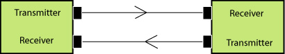
Fiber optic transmission systems (datalinks)
all work similar to the diagram shown above. They
consist of a transmitter on one end of a fiber and a
receiver on the other end. Most systems operate by
transmitting in one direction on one fiber and in the
reverse direction on another fiber for full duplex
operation.
Fiber Optic Transceiver
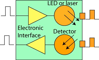
Most systems use a "transceiver" which includes both
transmission and receiver in a single module. The
transmitter takes an electrical input and converts it to
an optical output from a laser diode or LED. The light
from the transmitter is coupled into the fiber with a
connector and is transmitted through the fiber optic
cable plant. The light from the end of the fiber is
coupled to a receiver where a detector converts the
light into an electrical signal which is then
conditioned properly for use by the receiving equipment.
As
the use of links at 100Gb/s or more become common,
datalinks become more complex. Above about 25Gb/s,
the average limit for direct modulation of typical laser
sources, wavelength division multiplexing, parallel
optics and coherent fiber optic systems are used. In
addition coherent systems can be more effective to
overcome dispersion in long links. Read
more about coherent fiber optic systems.
Sources
for Fiber Optic Transmitters
The sources
used for fiber optic transmitters need to meet several
criteria: it has to be at the correct wavelength, be
able to be modulated fast enough to transmit data and be
efficiently coupled into fiber.
Four types of
sources are commonly used, LEDs, fabry-perot (FP)
lasers, distributed feedback (DFB) lasers and
vertical cavity surface-emitting lasers (VCSELs). All
convert electrical signals into optical signals, but are
otherwise quite different devices. All three are tiny
semiconductor devices (chips). LEDs and VCSELs are
fabricated on semiconductor wafers such that they emit
light from the surface of the chip, while f-p lasers
emit from the side of the chip from a laser cavity
created in the middle of the chip.
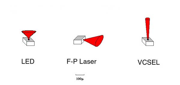
LEDs have much
lower power outputs than lasers and their
larger, diverging light output pattern makes them
harder to couple into fibers, limiting them to use with
multimode fibers. Laser have smaller tighter light
outputs and are easily coupled to singlemode fibers,
making them ideal for long distance high speed links.
LEDs have much less bandwidth than lasers and are
limited to systems operating up to about 250 MHz or
around 200 Mb/s. Lasers have very high bandwidth
capability, most being useful to well over 10 GHz or 10
Gb/s.
Because of their fabrication methods, LEDs and VCSELs
are cheap to make. Lasers are more expensive because
creating the laser cavity inside the device is more
difficult, the chip must be separated from the
semiconductor wafer and each end coated before the laser
can even be tested to see if its good.
Typical Fiber
Optic Source Specifications
| Device
Type |
Wavelength
(nm) |
Power
into
Fiber (dBm) |
Bandwidth |
Fiber
Types |
| LED |
850,
1300 |
-30 to -10 |
<250
MHz |
MM |
| Fabry-Perot
Laser |
850,
1310 (1280-1330) 1550 (1480-1650) |
0
to +10 |
>10
GHz |
MM,
SM |
| DFB
Laser |
1550
(1480-1650) |
0
to +25 |
>10
GHz |
SM |
| VCSEL |
850 |
-10
to 0 |
>10
GHz |
MM |
LEDs have a
limited bandwidth while all types of lasers
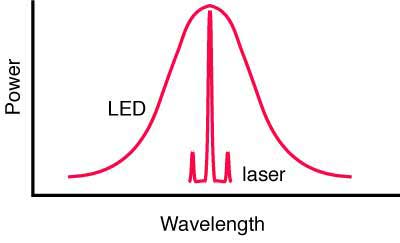
are very fast. Another big difference between LEDs
and both types of lasers is the spectral output. LEDs
have a very broad spectral output which causes them to
suffer chromatic dispersion in fiber, while lasers have
a narrow spectral output that suffers very little
chromatic dispersion. DFB lasers, which are used in long
distance and DWDM
systems, have the narrowest spectral width which
minimizes chromatic dispersion on the longest links. DFB
lasers are also highly linear (that is the light output
directly follows the electrical input) so they can be
used as sources in AM CATV systems.
The choice of these devices is determined mainly by
speed and fiber compatibility issues. As many
premises systems using multimode fiber have exceeded bit
rates of 1 Gb/s, lasers (mostly VCSELs) have replaced
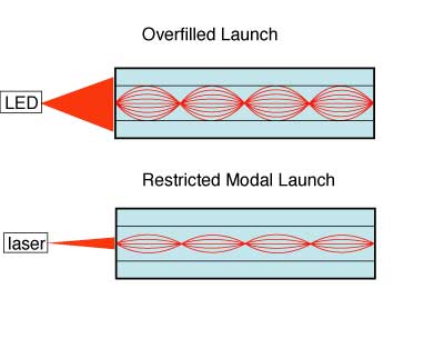
LEDs. The output of the LED is very broad but
lasers are very focused, and the sources will have very
different modal fill in the fibers. The restricted
launch of the VCSEL (or any laser) makes the effective
bandwidth of the fiber higher, but laser-optimized
fiber, usually OM3, is the choice for lasers.
The electronics
for a transmitter are simple. They convert an incoming
pulse (voltage) into a precise current pulse to drive
the source. Lasers generally are biased with a low DC
current and modulated above that bias current to
maximize speed.
More
technical information on LEDs and Lasers used as
fiber optic sources.
Detectors
for Fiber Optic Receivers
Receivers use
semiconductor detectors (photodiodes or photodetectors)
to convert optical signals to electrical signals.
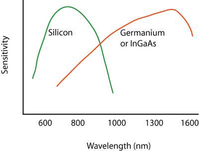
Silicon photodiodes are used for short wavelength
links (650 for POF and 850 for glass MM fiber). Long
wavelength systems usually use InGaAs (indium gallium
arsenide) detectors as they have lower noise than
germanium which allows for more sensitive receivers.
Very high speed
systems sometimes use avalanche photodiodes (APDs) that
are biased at high voltage to create gain in the
photodiode. These devices are more expensive and more
complicated to use but offer significant gains in
performance.
Data Protocols And Modulation Methods
In general, the demand is for transceivers with
higher bit rate capability but with low cost. Below 10 Gb/s transceivers
can be simpler, with one laser modulated with binary encoding, where
the laser transmits light for a "1" and is turned off for a "0". But the
limit for laser modulation is ~25-50 Gb/s. If one needs faster speeds
like 100Gb/s, there are several schemes used.
Parallel transmission: Multimode fiber with
limited bandwidth uses 4 or 10 lasers transmitting at 10G or 25G over an
equal number of fibers. It requires the use of array connectors (12 or 16 fibers in a connector) and many fibers.
WDM (wavelength division multiplexing):
Transmitters have several lasers transmitting over a single fiber.
Receivers split out the wavelengths to separate detectors. This has been
used since the 1990s for long distance telecom and more recently has
become widely used in data centers to reduce the numbers of fibers
needed. A scheme for WDM on multimode fiber has not gained much use.
PAM (pulse amplitude modulation): By using the
height of the pulse to also encode data, a transceiver using PAM4 can
double the data rate on a single fiber. A single laser can achiever
100Gb/s using PAM4 modulation. Higher data rates can use combined PAM4
channels with WDM.
Coherent transmission: Coherent transmission
uses a very complex transceiver that can achieve speeds up to terabits
per second over very long distances. It has primarily been used in long
distance and submarine links but cost reductions have led to some use in
high speed links for data centers.
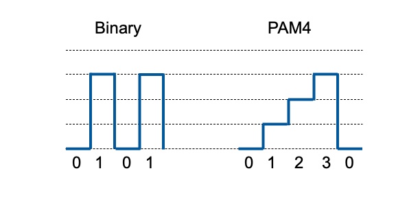
Binary vs PAM4 Modulation
Binary transmission simply turns the laser on for a 1 or 0. In a PAM4 encoded signal, the
bit has information in the pulse height, which means the bit can carry
two bits of information - "0, 1,2 or 3," twice as much information in
the same bit, doubling the information carrying capacity of the link. A PAM4 transceiver needs only one laser to achieve 100Gb/s data rates,
making it less expensive than a transceiver that has 4 lasers and a WDM.
The same technology can be leveraged for 400G also. PAM4 is not a fiber innovation. It has been used for years in electrical
communication circuits to increase bandwidth. But the implementation
requires some signal processing in the receiver which took some time to
implement in fiber optic transceivers.
Performance
Just as with
copper wire or radio transmission, the performance of
the fiber optic data link can be determined by how well
the reconverted electrical signal out of the receiver
matches the input to the transmitter. The
discussion of performance on datalinks applies directly
to transceivers which supply the optical to electrical
conversion.
Every
manufacturer of transceivers specifies their product for
receiver sensitivity (perhaps a minimum power required)
and minimum power coupled into the fiber from the
source. Those specifications will end up being the
datalink specifications on the final product used in the
field.
All
datalinks are limited by the power budget of the link.
The power budget is the difference between the output
power of the transmitter and the input power
requirements of the receiver. The receiver has an
operating range determined by the signal-to-noise ratio
(S/N) in the receiver. The S/N ratio is generally quoted
for analog links while the bit-error-rate (BER) is used
for digital links. BER is practically an inverse
function of S/N.
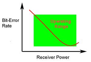
The
operating range of a data link will look like this figure
of BER
vs received optical power for a typical fiber optic
transceiver. There must be a minimum power at the
receiver to provide an acceptable S/N or BER. As the power
increases, the BER or S/N improves until the signal
becomes so high it overloads the receiver and receiver
performance degrades rapidly. More
on power budgets and the similar "loss budget" which is
the estimate of fiber optic cable plant loss.
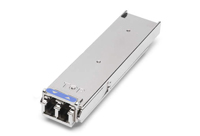
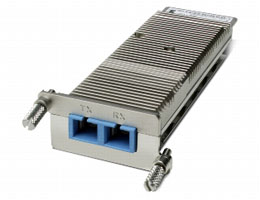
Packaging
Transceivers are
usually packaged in industry standard packages like
these XFP modules for gigabit datalinks(L) and Xenpak
(R). The XFP modules connect to a duplex LC connector on
the optical end and a standard electrical interface on
the other end. The Xenpak are for 10 gigabit networks
but use SC duplex connection. Both are similar to media
converters but are powered from the equipment they
are built into.
Test Your Comprehension
After you study this page and "More
on fiber optic datalinks", you
should test your comprehension here.
Table
of Contents: The FOA Reference Guide To Fiber Optics
