
Topic: Fiber Optic Cables With Multifiber/Array ConnectorsIncluding Polarity
and Testing
|
Table of Contents: The FOA Reference Guide |
Cables With Multifiber/Array Fiber Optic Connectors and Their Testing Issues Prefab cable systems and parallel array transmission systems for 40G/100G on multimode fiber generally use a multifiber array connector called a MPO or sometimes by a trade name MTP. These connectors use a large rectangular molded plastic ferrule with one or more rows of 12 fibers or 16 fibers. The connectors look like these Panduit PanMPO connectors. (Photo courtesy of Panduit) Note 1: These connectors are not generally considered field-installable. The ferrules should be factory installed and polished on polishing machines to get consistent results.They are usually factory terminated assemblies used for prefab cable systems. Some manufacturers offer prepolished splice versions but they are not widely used. If field installation is required, splicing on factory made breakout cables (MPO to pigtails) is recommended. Note 2: This page is provided to help users understand the complexity of testing these connectors. Several test equipment manufacturers offer equipment that can test these connectors for loss and polarity which greatly simplifies testing. 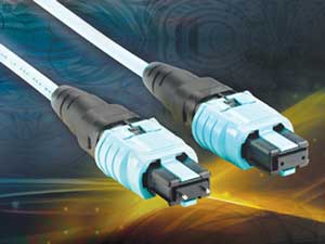
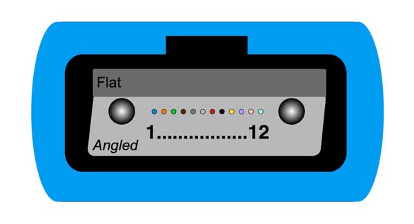
Note the two different connectors, one with pins sticking out from the end of the rectangular plastic ferrule from the connector on the left and the other on the right has holes instead of pins. The MPO connector relies on the pins and holes to align the ferrules for the entire row(s) of fibers between the pins. As shown in the drawing below, the MPO connector can have 1 to 6 rows of 12 fibers each, although only two versions, 12 or 24 fibers, have gained significant market acceptance. The larger circles represent the alignment pins/holes and the small circles the fibers. (Note a 16 fiber per row connector is being proposed.) 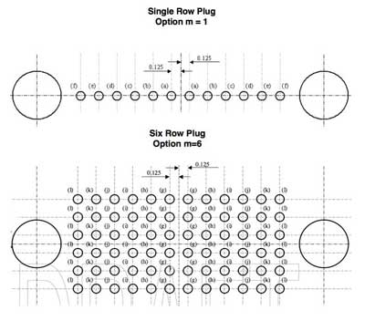 When mating two MPOs, one connector must have pins and another holes, usually referred to as "pins" and "holes" or "no pins." That nomenclature is more common in the fiber optic industry than describing them as male/female as they are described in the drawing below. Mating alignment is done by the guide pins and holes but there must be a mating adapter to hold the connector bodies and let them snap into place. The adapter also aligns the MPO connector keys, which may be up or down in relation to the numbering of the fibers. In use, the MPO connectors form a "plug and jack" style connector, where the plug is a no-pin connector and a jack is a pin connector with mating adapter. 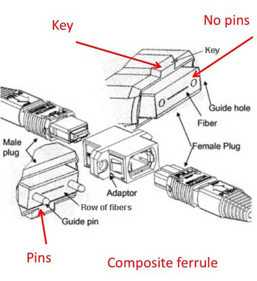 These options for pins/holes and key up/down means that there are 4 types of MPO connectors and a patchcord could have as many as 16 variations (4 on each end), although it's really half that many if you are looking at the fiber alignment rather than absolute fiber numbering schemes. Note: Several manufacturers offer MPO connectors that are "switchable" allowing them to be changed from pins to no pins or reversing the location of the key. These connectors are highly preferred for testing and may be a convenience when building systems where one needs to switch connector types. There are also multimode and singlemode versions of the MPO. The multimode versions generally have flat ferrules but the singlemode versions have angled ferrules at the same 8 degree angle used on regular single fiber APC connectors. For very high speed MM networks, some transceivers require APC multimode connectors which are color coded green like singlemode connectors. However the APC singlemode and multimode ferrules do not have an angle across the entire surface, only about 2/3 of the ferrule, so when two ferrules are mated, only the center 1/3 of the ferrule in actually mating. To further complicate the variations on MPO connectors, there appears to be no standard on the orientation of the angled surface - it can be toward the key or away from the key. Check before you mate. 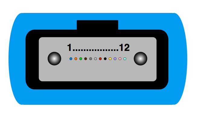
 Multimode MPO has flat ferrule (L) while singlemode ferrule is angled on 2/3 of the end of the ferrule. 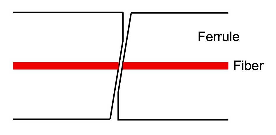 Due to the endface geometry, only about 1/3 of the SM MPO connector ferrules face actually mate. Note: MM APC connectors are, like SM, only supposed to be mated to another APC connector. TO identify APC connectors, green coloring on the connector body or strain relief is used to identify them. Anyway, these variations create a very difficult situation for users who are forced to specify the exact configuration of each cable and connector. Panduit with the PanMPO shown above and several other manufacturers have faced this issue and produced a connector that allows changing both pin and key configurations with a simple tool. This connector is highly recommended, especially for test reference cables where one may encounter many different configurations. MPO cables come in two variations (in addition to the pins/holes and keying options), cables with MPOs on either end or breakout cables with an MPO on one end and single fiber connectors on the other end. 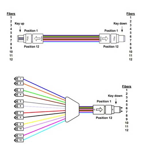 MPO-MPO cables are used as backbone cables in prefab or parallel cable systems and patchcords in parallel optics transmission systems. Breakout cables can be plain for use in testing or in modules (Corning module shown below) for use in prefab cabling. 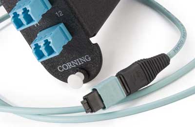 There are even MPOs with rugged sealed housings used for prefab assemblies for OSP use. 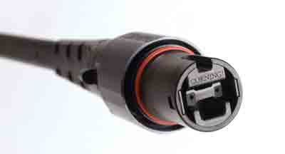 Photos
courtesy Corning Photos
courtesy CorningBelow is a drawing of a prefab cabling system using MPO-SC breakout modules like the one shown above. In all diagrams, we note the pins at the interface. Breakout modules with single fiber connectors on one end and MPOs on the other end will generally have pin connectors inside mating adapters. In parallel cable systems, generally the cable in the middle is the permanently installed cable and will have pins and be terminated in a mating adapter, forming a jack for the no-pin patchcords. However the TIA spec for cabling has more than 38 pages of possible combinations for these cable plants, varying in pins/no-pins, keying, types of connectors, color codes and numbering schemes. The only way to figure out what you have is to use the manufacturer's documentation since you cannot inspect inside the modules or cables for color codes. 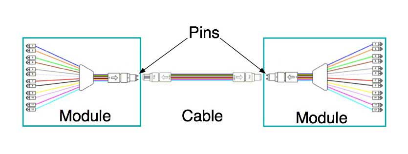 And here is a similar drawing of a prefab cabling system using MPO connectors throughout to connect to a transceiver for parallel optics transmission. 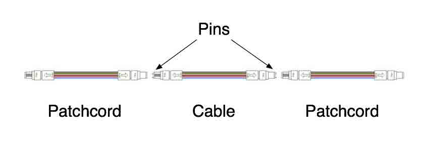 Here is a MPO connector with parallel optics transceiver and pinouts for 40G and 100G. Generally, the backbone cable that is permanently installed will end in connectors with pins inside mating adapters, effectively creating a "socket" type connection. Patchcords will have no pins since they are subject to damage because they simply protrude from the connector. Transceivers will be set up as jacks also, with pins inside the transceiver socket. For 40G parallel (40Gbase-SR4) which has 4 10G channels, the pin arrangement is:
MPO Polarity As mentioned above, the TIA spec for cabling (TIA-568) has more than 20 pages of possible combinations for MPO cable plants, varying in pins/no-pins, keying, types of connectors, color codes and numbering schemes.To understand the issues, start with the standard fiber color codes. 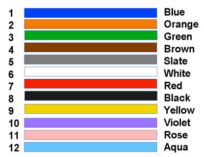 Terminated in a MPO connector logically and per industry convention, where the connector pins are also numbered 1-12, you would have a connector like this: But when you start making cables, the diversity begins. There are 3 types of cables in TIA-568, called type A, B and C. Here is what they look like: Type A Cables 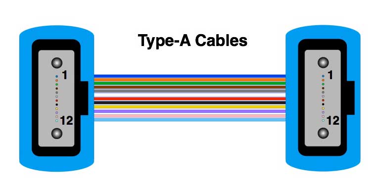 In a Type A cable, the #1 fiber is terminated in the #1 hole in each connector. Thus this would be a "straight through" cable. Type B Cables 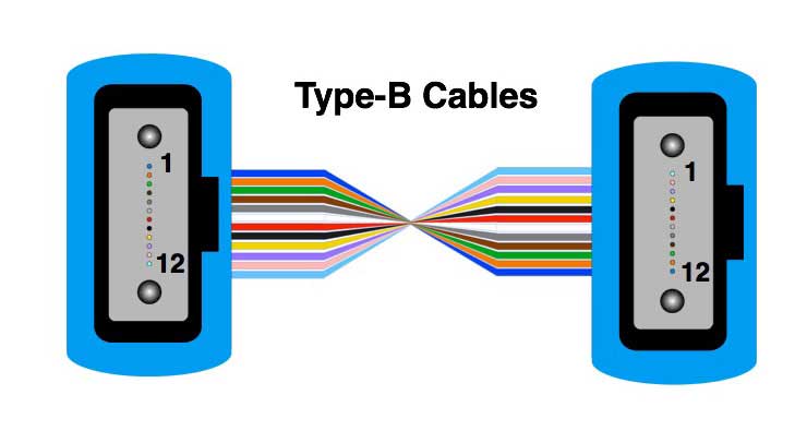 In a Type B cable, the fibers are reversed. This is accomplished by reversing the fiber orders in the connectors so fiber #1 goes in connector hole #12, #2 foes in hole #11 to #12 fiber in #1 hole. This is a cable you would use it you have a 40G parallel optics link and use a single cable to connect the transceivers (see diagram on the parallel optics for 40G above since you must reverse conductors at some point. There are other ways to do the reversal, e.g. with a mating adapter if you have several cables in the cable plant. See the Type B mating adapter below. Type C Cables 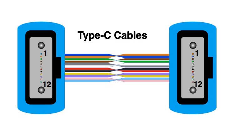 Type C cables have the fibers divided into 6 pairs which are reversed. They are intended to be used with prefab cabling systems which will connect to breakouts (cables or modules) individual 2-fiber channels on each end as shown above. Reversing the pairs means that regular duplex patchcords will have a crossover needed to allow transmitters to connect to receivers and vice versa. Needless to say, this cable could prove to be a big problem if you tried to use this as a cable for 40G links, as the reversed pairs will need to be reversed a second time with another of these cables. It seems better to not use this cable but put the crossovers into modules on each end that break out the MPO connection to duplex connectors. Mating Adapters Notice that a MPO connector has a key at the top. Mating adapters come in two varieties, Type A and Type B, depending on the key location. Here are the differences. Type A Mating Adapters 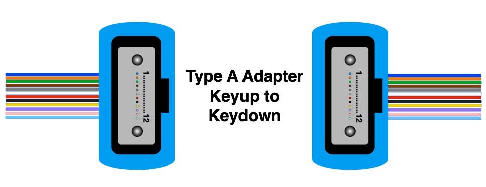 MPO Type A Mating Adapters mate the connectors with the key of one connector in one direction and the key of the other in the opposite direction - called "Keyup to Keydown." This key alignment means that pin 1 of one connector is aligned with pin 1 of the other connector, providing a straight through connection for each fiber - e.g. blue to blue, orange to orange, all the way to aqua to aqua. This means fiber color codes are maintained through the connection. Type B Mating Adapters 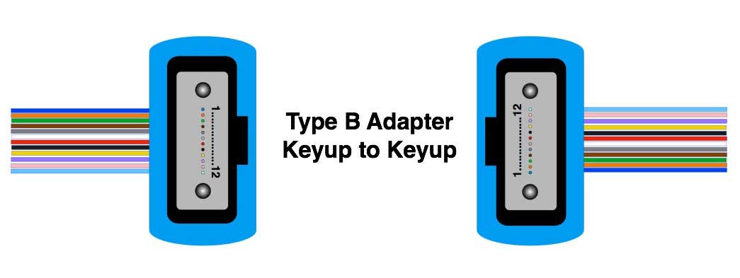 Type B Mating Adapters align the two connectors key to key or "Keyup to Keyup" and swap the color codes of the fibers, similar to what happens in a Type B cable. Swapping fibers is necessary for aligning fibers for a 40G transceiver. Which Configuration Do You Need To Use? The type of MPO components you choose depends on your network components needs - that is how you need to connect appropriate trasmitters and receivers in your network. Unfortunately manufacturers of these components and cable assemblies do not agree on exactly how to make those connections, so we have all this choice and 23 pages in TIA 568 on the official options, although many more exists. One thing to remember is that adding Type B components (cables or mating adapters) swaps the fibers while Type A components (cables or mating adapters)does not affect the positions of the fibers. Thus if you need to reverse fibers as in using a MPO patchcord to directly connect two transceivers, use Type B components. If you do not want to reverse fibers, use Type A components. And if you have a cable plant with an odd number of Type B components, it will have the fibers reversed, and even number will have the fibers in the original configuration. It may make more sense to keep the backbone all Type A cables and then make the swaps in modules or patchcords on each end. MPO Testing Testing cables with MPO connectors can be challenging. Cleaning and inspection are important but difficult. You must establish the color code configuration to understand the path of an given fiber in order to figure out how to connect to one fiber for testing. There are many options on how to test depending on the configuration of the cable plant, e.g. all MPO connectors or breakouts into individual fiber or duplex fiber connectors. Most test options will have higher uncertainty than typical single fiber testing. The tech doing the work must make decisions based on the cabling configuration and the test equipment available. Watch for test results showing higher loss as that may indicate that reference test cables are wearing out. The problems with testing MPO cables and cable plants include: 1) there are few insertion loss test sets designed to interface with multifber connectors like the MPO, but their use is highly recommended as they will save large amounts of time and provide more accurate results. 2) the MPO connectors come in several varieties making it hard to have the right reference cables (although the switchable connectors like the PanMPO shown above allows changing pin/hole and keying to allow mating to virtually any MPO connector 3) MPO connectors do not have the mating durability of single-fiber ceramic ferrule connectors so reference cables may have significantly shorter lifetimes before all test losses increase due to connector wear 4) the connectors are hard to clean properly 5) Most MPO assemblies are multimode fiber of the OM3 or OM4 variety and are intended for use with high speed multimode systems. These systems have very low power budgets, typically <2dB so measurements need to be accurate. Since these high speed systems use VCSEL sources, using a mode conditioner (mandrel wrap or EF compliant source) is important as it will give more precise measurements and usually a lower loss than a typical 850nm LED test source. Generally, one would say one should test these connectors using a 3-cable reference as one would use in a plug/jack connector pair. See Table 1. The complication is the configuration of the cable plant and the total of 12 fibers in each cable. Using a 3 cable reference with a typical light source and power meter or OLTS would require the usual 3-cable reference process being repeated 12 times - once for each fiber in the cable - which makes it hard to keep the cables clean during the process and causes excess wear on the reference connectors. What we have done is to provide several scenarios for testing both prefab cable systems and parallel cable systems and recommendations for various solutions. See below. As you look at all these diagrams, remember that the PanMPO offers the ability to change gender and keying, simplifying the testing of these systems. Table 1. Reference methods for fiber optic loss testing.
Here is a complete rundown on all standard methods of testing fiber optic cables. Here are the FOA Standards for testing fiber optic cables. Cleaning and Inspection MPO connectors are polished so that the fibers extend a small amount from the end of the ferrule so when mated the fibers actually touch. You can see that exaggerated in this interferometer scan of a MPO ferrule. With fibers protruding, it's very important to clean the end of the connector carefully. 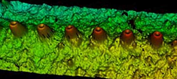 MPO connectors are very sensitive to dirt and contamination. The ferrules are large and hard to clean and inspect. Most microscopes do not have adapters for MPO connectors and those that do are adapted from single fiber microscopes and only see a small section of the ferrule so you have to scan manually along the ferrule to inspect the entire ferrule and every fiber. 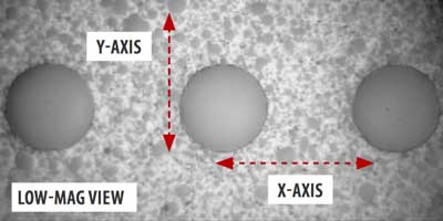 JDSU
photo JDSU
photoCleaning is also a problem because of the pins and holes. Most dry cleaners clean only between the pins so dirt may build up around the pins of in the holes causing alignment problems. It is recommended to be especially careful to keep these connectors covered and protected when not in use. Testing Prefab Cabling Systems Note: Several manufacturers of test equipment offer special test sets for MPO cable assemblies. The loss test sets have MPO connector interfaces and test all fibers with one connection. They need to not only test loss but also polarity as noted above. The complexity of testing MPOs with a single channel OLTS or light source and power meter makes these test sets highly desirable for the tech working with MPO cable plants. Special microscopes for viewing these connectors are also available and highly recommended. If you are doing OTDR testing, the only practical method is to use a regular single channel OTDR and breakout cables. Testing insertion loss of a modular prefab cabling system with single fiber connector breakouts like the module shown in the photo above is straightforward, it’s just like a regular cable plant because it ends in single fiber connectors. Use a test source and appropriate launch cable, 1 cable “0dB” reference and test each fiber in turn. This will give insertion loss including all fiber and connections. If there are problems, it may be necessary to test the parallel cable (see directions below) or use a very high resolution OTDR. 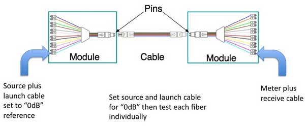 If you need to test the prefab cable plant with an OTDR, the test is also straightforward since the cable plant ends in single fiber connectors. 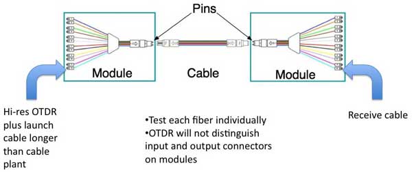 If you are doing an OTDR test, use both a launch and receive cable and make sure the launch cable is longer than the cable plant under test to reduce the chance of getting ghosts. Ghosts can be a major problem in short cable plants with lots of reflective connectors. Use the shortest possible test pulse on the OTDR for maximum resolution and to minimize the possible saturation of reflectance pulses. Even so, you will probably not be able to distinguish the connectors on each side of the modules. You should get a trace like this: 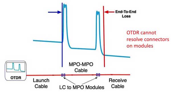 You can test the total loss of the cable plant by placing markers before and after the ends of the cable plant. You will see the total loss of the input and output connectors on the breakout modules so if it appears to have high loss or reflectance, you will need to clean and retest. You might also need to remove the module and test it individually which creates another problem, testing a hybrid cable with a single fiber on one end and an MPO on the other end. See testing the parallel cable below. You will repeat this test for each fiber in the cable, all 12 or 24 of them. What to look for in OTDR tests – high loss and high reflectance. You may also see “gainers” caused by fibers with different backscatter coefficients, including at interfaces of regular and bend-insensitive fibers. You may also use the LSA (least squares) test on the OTDR to make an end-to-end cable plant loss measurement. Place the LSA event marker at the beginning of the cable plant and the LSA horizontal markers on the launch and receive cables. This will give a more accurate measurement of the cable plant loss. 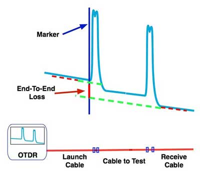 Testing Parallel Cabling- Insertion Loss Testing a parallel cable plant with MPO connectors is - well a test equipment applications engineer once called it “impossible” in an industry meeting. The problem is few test sets have adapters for these multifiber array connectors so you need to find ways to adapt typical singe fiber test equipment to testing them. In doing so, you must compromised the typical insertion loss test by adding adapter cables from the MPO connector to SC type connectors more commonly used on test equipment. In doing so, you add extra connections and uncertainty to the tests. 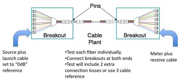 Testing a parallel cabling system terminated in MPO connectors is more difficult and less accurate. You have to deal with male/female connectors (pin/no pin) and the fact that there are few testers that can accommodate the 12-pin MPO connector. If you are using a typical single fiber fiber optic test source and power meter, your best bet is to add breakout cables to both MPO ends of the cable plant and then test the cable plant including the breakouts. In making the measurement this way, your loss will be higher than the actual cable plant by the loss of the connectors on the breakouts when connected to the launch and receive reference cables. That will add approximately 0.5-0.8dB +/-0.2 dB to the actual loss of the cable plant under test. You can partially compensate for this by using a 3-cable reference but will increase uncertainty. In consideration of the uncertainty of the measurement, it could be preferable to use an OTDR to test the cable plant and get reflectance data at the same time. Note 1 – there are tools to allow some MPO connectors (Panduit PanMPO) to be changed from pin to no-pin or vice versa and change keying. Note 2 – MPO connectors do not have the mating durability of ceramic ferrule connectors so cleaning and careful handling are important and they may not last for as many test connections before showing higher loss. Another option is to use a single output source which connects each fiber in the cable and a meter with a large area detector and MPO adapter. You manually change the source from fiber to fiber but the meter remains fixed. This method will not confirm the polarity of the connection unless your carefully note the fiber the source is connected to each time. 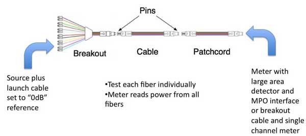 Another option is to use a source with breakout and a meter with a large area detector or a breakout and a single fiber meter. You switch the source from fiber to fiber using the switch which has relatively low variability from fiber to fiber. 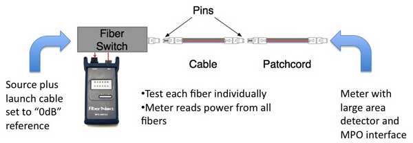 (or
breakout cable and meter) (or
breakout cable and meter)Finally, there are testers available with MPO interfaces designed to test these cables efficiently. While these testers are expensive, they are probably the best way to test these cables. 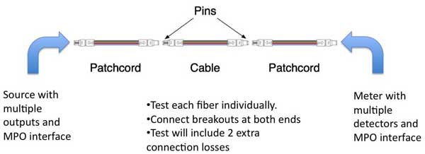 Testing a parallel cable plant requires adding in two breakout cables to access each end of the cable plant. If the breakouts are long enough, about 20m when using a high-resolution OTDR, you will be able to see the actual connection to the MPO connections on the cable plant. Notice the location of the pins. We’re assuming you are testing from the ends of the cables that will be connected to the network electronics. If you are testing an installed cable plant at the wall outlets, you will need a breakout cable with MPO connector without pins. OTDR testing follows the same routine, but here are a couple of hints. Use a launch cable longer than the fibers you are testing so any ghosts will be outside the trace of the cable under test, avoiding confusing traces. Use a relatively long receive cable also so you measure the connectors on both ends of the cable. Use the shortest possible test pulse on the OTDR for maximum resolution and to minimize the possible saturation of reflectance pulses. Even so, you will probably not be able to distinguish the connectors on each side of the modules. You will see the total loss of the input and output connectors so if it appears to have high loss or reflectance, you will need to clean and retest. You will repeat this test for each fiber in the cable, all 12 or 24 of them. What to look for in OTDR testing – high loss and high reflectance. You may also see “gainers” caused by fibers with different backscatter coefficients, including at interfaces of regular and bend-insensitive fibers. Testing Parallel Cabling - OTDR Testing OTDR testing a parallel cable plant requires adding in two breakout cables to access each end of the cable plant. If the breakouts are long enough, about 20m when using a high-resolution OTDR, you will be able to see the actual connection to the MPO connections on the cable plant. OTDR testing follows the same routine as usual OTDR tests, but here are a couple of hints. Use a launch cable longer than the fibers you are testing so any ghosts will be outside the trace of the cable under test, avoiding confusing traces. Use a relatively long receive cable also so you measure the connectors on both ends of the cable. Use the shortest possible test pulse on the OTDR for maximum resolution and to minimize the possible saturation of reflectance pulses. Even so, you will probably not be able to distinguish the connectors on each side of the modules. You will see the total loss of the input and output connectors so if it appears to have high loss or reflectance, you will need to clean and retest. You will repeat this test for each fiber in the cable, all 12 or 24 of them. 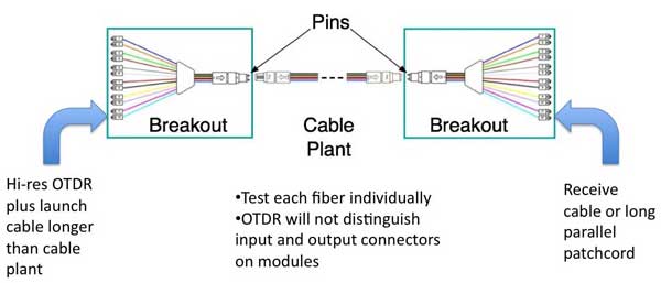 See the explanation above for interpreting OTDR traces. What to look for in OTDR testing – high loss and high reflectance. You may also see “gainers” caused by fibers with different backscatter coefficients, including at interfaces of regular and bend-insensitive fibers. OTDR testing can also be done with a switch to connect the OTDR and a long parallel launch cable following the switch. 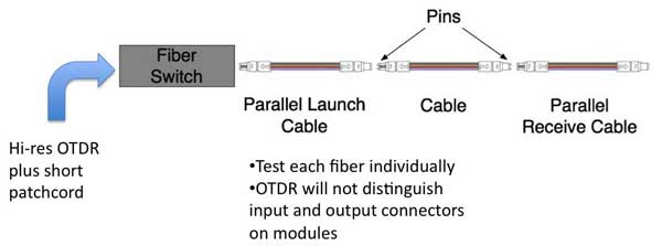
Summary & Recap Testing cables with MPO connectors can be challenging. Cleaning and inspection are important but difficult. There are many options on how to test depending on the configuration of the cable plant. Most test options will have higher uncertainty than typical single fiber testing. The tech doing the work must make decisions based on the cabling configuration and the test equipment available. Watch for test results showing higher loss as that may indicate that reference test cables are wearing out. Here is a complete rundown on all standard methods of testing fiber optic cables. Here are the FOA Standards for testing fiber optic cables. |
|||||||||||||||||||||||||||||||||||
| (C)2019,
The Fiber Optic Association, Inc. FOA Guide Table of Contents |