Fiber
Optic Data Links
The
purpose of this document is to define a “fiber optic
datalink,” its purpose, design and performance. It is
intended to provide guidance for the designer of
datalinks or communications systems and the installer of
fiber optic systems who must verify the performance of
the datalink including the cable plant installed for its
operation.
Datalinks
A fiber optic datalink is a communications subsystem
that connects inputs and outputs (I/O) from electronic
subsystems and transmits those signals over optical fiber.
In this function, a fiber optic datalink operates as an
alternative to copper cabling or a wireless subsystem. In
typical applications, a fiber optic datalink acts as a
communications medium attached to electronics on either
end that provide the other services necessary for
communications over the link. In the OSI (Open Systems
Interconnection) Network Model, the datalink is basically
the first layer, called the Physical Layer or PHY.
A
fiber optic datalink consists of fiber optic transceivers
or individual transmitters and receivers at either end
that transmit over optical fibers.
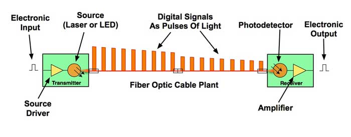
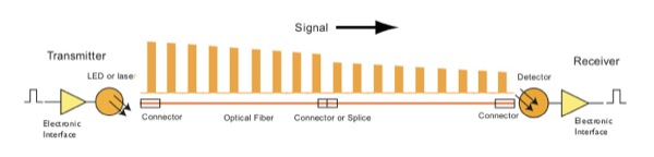
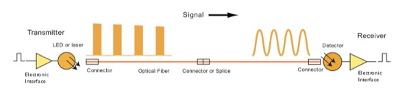
In operation, the fiber optic datalink gets an electrical
pulse input from an electronic system. In the transmitter,
a source driver sends current through a source, typically
a laser but sometimes a LED, which creates a pulse of
light. The pulse of light from the source is coupled into
an optical fiber that is part of a fiber optic cable
plant.
The pulse travels down the fiber where it is attenuated by
the fiber and suffers loss from fiber joints created by
splices or connections. At the receiver, the light pulse
is converted to an electrical pulse by a photodetector,
amplified by the receiver circuitry and converted to an
electrical pulse compatible with the communications
equipment it connects.
Signals and Protocols
Fiber optic datalinks may transmit signals that are
either analog or digital and of many different, usually
standardized, protocols, depending on the communications
system(s) it supports. Datalinks may be protocol
transparent but may also include data encoding to provide
more robust data communications. Datalinks may be
specified by the application or standardized network (e.g.
Ethernet) they are intended to support or by the types and
bandwidth of signals they are designed to transmit.
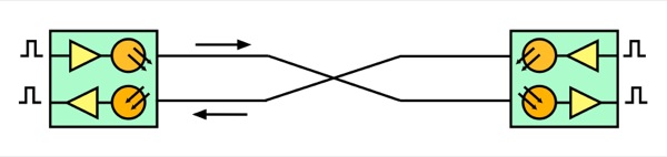
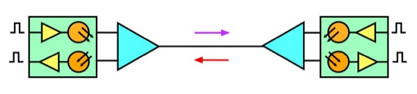
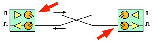
Components Of A Fiber Optic Datalink Using 2 Fibers For
Full Duplex Operation
The typical datalink transmits over two fibers for full
duplex links, one fiber in each direction. The fibers may
be of any type, multimode (graded index or step index) or
singlemode.
Wavelength division multiplexing allows sending multiple
signals over the same fiber simultaneously.
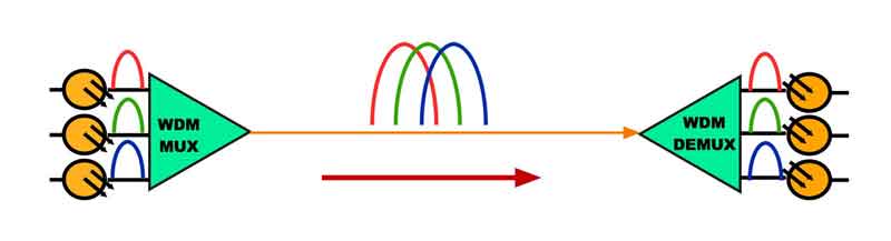
Some links may use wavelength-division multiplexing to
transmit bi-directionally over a single fiber as in FTTH
PONs passive optical networks or OLANs, optical LANs. Some
links may allow transmission at several wavelengths of
light simultaneously over a single fiber in each
direction, called wavelength-division
multiplexing.
Components
Of A Fiber Optic Datalink Using A Single Fiber
Extremely long cable plant lengths may require
regeneration using repeaters, essentially datalinks in
series. Optical
fiber amplifiers may be used as repeaters in long
singlemode systems. Singlemode systems using fiber
amplifiers and wavelength-division multiplexing may
require concern for nonlinear effects from high optical
power involved.
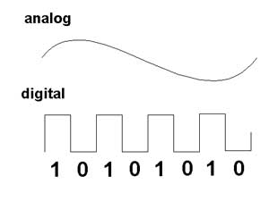
Analog
or Digital?
Analog
signals are continuously variable signals where the
information in the signal is contained in the amplitude
of the signal over time. Digital signals are sampled at
regular time intervals and the amplitude converted to
digital bytes so the information is a digital number.
Analog signals are the natural form of most data, but
are subject to degradation by noise in the transmission
system. As an analog signal is attenuated in a
cable, the signal to noise ratio becomes worse so the
quality of the signal degrades. Digital signals can be
transmitted long distances without degradation as
the signal is less sensitive to noise.
Fiber
optic datalinks can be either analog or digital in
nature, although most are digital. Both have some common
critical parameters and some major differences. For
both, the optical loss margin or power budget is most
important. This is determined by connecting the link up
with an adjustable attenuator in the cable plant and
varying the loss between transmitter and receiver until
one can generate the curve shown above. Analog datalinks
will be tested for signal to noise ratio to determine
link margin, while digital links use bit error rate as a
measure of performance. Both links require testing over
the full bandwidth specified for operation, but most
data links are now specified for a specific network
application, like AM CATV or RGB color monitors for
analog links and SONET, Ethernet or Fibre Channel for
digital links.
Transceiver
A
fiber optic transceiver used on each end of a link
includes a transmitter and receiver that convert
electrical signals to optical signals and vice versa for
transmission over optical fiber. Appropriate interfaces
are included in the datalink to mate with the electrical
and optical signals it connects with. These are
typically standardized electrical and fiber optic
connectors.
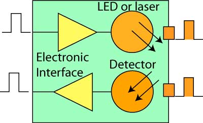
Fiber
optic transceiver block diagram
The transmitter consists of an electrical input and
signal conditioning circuitry to drive an optical
source, a light-emitting diode or laser that provides
the electrical to optical conversion and alignment
hardware for coupling of the optical signal into an
optical fiber for transmission.
The receiver consists of a detector that connects to the
optical fiber to accept an optical signal, convert the
optical signal that has been transmitted through the
optical fiber to an electrical signal and conditioning
circuitry that creates an electrical output compatible
with the communications system.
Transceivers are dedicated to one type of fiber
determined by the distance and bandwidth of the
communications being transmitted. Multimode fiber may be
used for shorter and/or slower datalinks while
singlemode fiber is used for longer links. The source in
the transceiver will also depend on the application.
LEDs are used for slower (<~100 Mb/s) multimode links
and VCSELs are used for faster multimode links.
Some standard networks have options for using singlemode
1310nm lasers on multimode fiber. There are currently
four types of multimode fiber used for datalinks,
designated OM1-4. OM-1 is a fiber with larger core (62.5
microns) used primarily in legacy systems with LEDs at
850 or 1300 nm wavelengths. Faster multimode links use
OM-2, OM-3 or OM-4 fiber with a 50 micron core,
generally the faster fibers designated OM-3 or OM-4
which are optimized for 850 nm VCSELs.
Singlemode
systems use lasers at 1310 or ~1550nm. 1310nm lasers are
used for shorter links. The longer wavelengths around
1550 nm are used for long links and those using
wavelength-division multiplexing. There are several
specialized singlemode fibers which are optimized for
special applications.
As
the use of links at 100Gb/s or more become common,
datalinks become more complex. Above about 25-50 Gb/s,
the average limit for direct modulation of typical laser
sources, amplitude modulation, wavelength division multiplexing, parallel
optics and coherent fiber optic systems are used. In
addition coherent systems can be more effective to
overcome dispersion in long links. Read
more about coherent fiber optic systems.
More
on fiber optic transceivers and their components
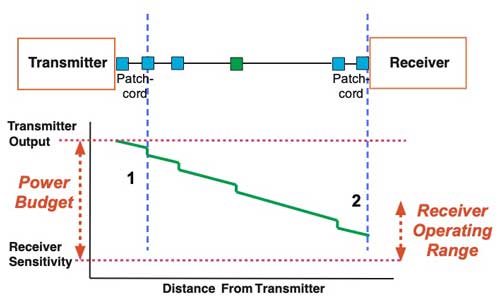
Power Budget
All
datalinks are limited by the power budget of the link.
The power budget is the difference between the output
power of the transmitter and the input power
requirements of the receiver. The receiver has an
operating range determined by the signal-to-noise ratio
(S/N) in the receiver. The S/N ratio is generally quoted
for analog links while the bit-error-rate (BER) is used
for digital links. BER is practically an inverse
function of S/N.
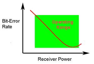
BER vs received optical power for a fiber optic
transceiver
The operating range of a data link will look like the
graph above. There must be a minimum power at the
receiver to provide an acceptable signal to noise ratio
(S/N) or Bit Error Rate (BER, which is inversely
proportional to S/N.) As the power increases, the BER or
S/N improves until the signal becomes so high it
overloads the receiver and receiver performance degrades
rapidly. If the receiver is overloaded, one can use attenuators
to reduce the power to an acceptable level.
The power of the receiver is determined by the output
power of the transmitter diminished by the loss in the
cable plant primarily but other factors may affect power
budget performance. When the power budget is inadequate
for the loss in the cable plant, higher power
transmitters or more sensitive receivers or higher
bandwidth cable plant are required.
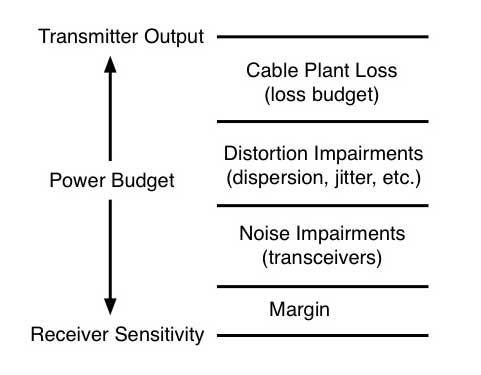
Contributions
to link power budget.
Link power budget
Transceivers may be components intended to be built into
electronic subsystems to create communications
equipment. Standalone transceivers may be sold as media
converters to convert signals from electrical on copper
cabling to fiber optics. Built-in transceivers are
generally powered by the communications equipment in
which they are installed. Media converters are powered
by separate sources of electrical power.
More on
power budgets and the similar "loss budget" which is
the estimate of fiber optic cable plant loss.
Fiber Optic Cable Plant
A
fiber optic datalink transmits signals as pulses or
varying light over optical fibers that are included in a
fiber optic cable plant. The permanently installed cable
plant consists of an optical fiber cable designed to
protect the fibers, which is installed, spliced and
terminated with proper hardware to mate with the
datalink transceivers. The cable plant must be selected
and installed to withstand the environment in which it
is installed. The cable plant is typically terminated at
outlets or patch panels near the communications
equipment. The installed cable plant is typically
connected to the transceivers by short patchcords.
The fiber optic cable plant must be compatible with the
performance parameters of the transceivers for the link
to operate properly. This includes types of fiber and
connectors, optical loss and bandwidth of the cable
plant. For the cable plant, a loss budget must be
calculated to estimate its loss and a power budget to
determine if the planned communications system will
operate over the cable plant.
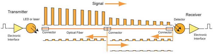
Fiber polarity is important for design and
documentation. Since the transmitter must be connected
to the receiver for the link to operate, there must be a
crossover in the fiber pair at some point in the cable
plant. Generally, the permanent cable plant is installed
straight through, with fiber 1 connected to fiber 1 on
each end, and so forth. Since the link requires one
crossover, that is accomplished by a crossover patch
cord on one end of the link. The location of crossover
patchcords should be limited to one area, e.g. the main
equipment room, so all duplex patch cords at that
location are crossover cables while straight through
cables are used at all other locations.
Cable Plant Performance
Parameters
The
factors that determine the required performance
parameters for a fiber optic datalink are those that
define the communications signals to be carried on the
link (the data bitrate (digital transmission) or
bandwidth (analog transmission) at which the link
operates), the length of the link and the specifications
(bandwidth and optical loss) of the fiber optic cable
plant. These factors determine the types of transceivers
and cable plant components that must be chosen for a
communications system.
The two major factors of concern in link design and
testing after installation are the loss of the cable
plant and the bandwidth.
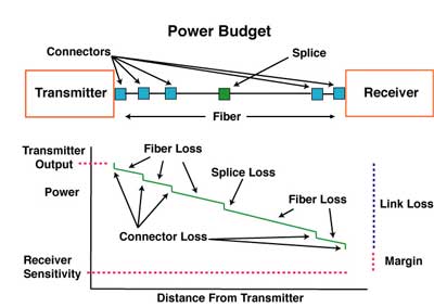
Cable
Plant Loss
The loss of the cable plant is determined by the summation
of the loss in the cable plant due to fiber attenuation,
splice loss and connector loss. In some cases the fiber
attenuation may be increased by improper installation of
the cable. As a signal travels down the fiber, the signal
will be attenuated by the optical fiber and reduced by the
loss in connectors and splices.
Loss of signal by attenuation in the cable plant
Loss Budgets
For
each cable plant designed, one must calculate a loss
budget. The loss budget estimates the loss of the fiber
in the cable plant by multiplying the length (km) by the
attenuation coefficient (dB/km), then adding the loss
from connectors and/or splices determined by the number
of connectors and/or splices times the estimated loss
each to get the total estimated loss of the cable plant.
The cable plant loss budget must be lower than the power
budget of the link transceivers (see below) for the link
to work properly.
Dispersion
Dispersion
or pulse spreading limits the bandwidth of the link.
Transceivers have some dispersion caused by the
limitations of the electronics and electro-optical
components but most of the dispersion comes from the
limited bandwidth of the fiber in the cable plant.
Dispersion of signal in the cable plant
Dispersion in multimode optical fiber occurs by modal
dispersion or chromatic dispersion. Modal dispersion is
caused by the different velocities of the various modes
being transmitted in the fiber. Chromatic dispersion is
caused by the different velocities of light at different
wavelengths.
Singlemode fiber also causes dispersion, but generally
only in very long links. Chromatic dispersion has the
same cause as multimode fiber, the differences in the
speed of light at different wavelengths. Singlemode
fiber may also suffer from polarization-mode dispersion
causes by the different speeds of polarized light in the
fibers.
The transceiver must be chosen to provide proper
performance for the communications system’s requirements
for bandwidth or bitrate and to provide an optical
transmitter output of sufficient power and receiver of
adequate sensitivity to operate over the optical loss
caused by the cable plant of the communications system.
The difference in the transmitter output and receiver
sensitivity defines the optical power budget of the
link.
The cable plant components, optical fiber, splices and
connectors, are chosen to allow sufficient distance and
bandwidth performance with the transceivers to meet the
communications system’s optical power budget
requirements. The power budget of the link defines the
maximum loss budget for the cable plant. The maximum
link length will be determined by the power budget and
loss budget for low bit rate links that will be derated
for dispersion for higher bandwidth links.
Most standardized communications systems will specify
the performance of the components including interfaces
to the electronic I/O and types of fiber supported for
various distances. Systems standards may also include
specifications for fiber optic connector type, primarily
at the transceiver. Most communications systems with
short links have options for both multimode and
singlemode fiber while longer links use only singlemode
fiber. All networks may provide guidance as to the types
or grades of fiber needed to support certain
applications.
Every manufacturer of datalinks components and systems
specifies their link for receiver sensitivity (perhaps a
minimum power required) and minimum power coupled into
the fiber from the source. Typical values for these
parameters are shown in the table below. In order for a
manufacturer or system designer to test them properly,
it is necessary to know the test conditions. For data
link components, that includes input data frequency or
bitrate and duty cycle, power supply voltages and the
type of fiber coupled to the source. For systems, it
will be the diagnostic software needed by the system.
Typical
Fiber optic link/system performance parameters
| Link
type |
Source/Fiber
Type |
Wave-
length
(nm)
|
Transmit
Power (dBm) |
Receiver
Sen- sitivity (dBm) |
Margin
(dB) |
| Telecom |
laser/SM |
1300/1550 |
+3 to -6 |
-30 to -45 |
30 to 40 |
|
DWDM |
1550 |
+20 to
0 |
-30 to -45 |
40 to 50 |
| Datacom |
LED/VCSEL |
850 |
-3 to -15 |
-15 to -30 |
3 to
25 |
|
LED/laser |
1300 |
-0 to -20 |
-15 to -30 |
10 to 25 |
| CATV(AM) |
laser/SM |
1300/1550 |
+10 to 0 |
0 to -10 |
10 to 20 |
Within
the world of data communications links and networks,
there are many vendor-specific fiber optic systems, but
there are also a number of industry standard networks
such as Ethernet which have fiber optic standards. These
networks have agreed upon specifications common to all
manufacturers' products to insure interoperability. This
page in FOA Tech Topics shows a summary of
specifications for many of these systems.
Reflectance
Reflectance refers to the light reflected at a connection
or mechanical splice. Some light is reflected back toward
the source and may sometimes be reflected many times in
short cables, creating a source of noise from the fiber
optic cable plant. If the source is a laser in a
singlemode link, the light reflected from a connection
near the source can cause problems with the laser also. In
short singlemode links it is common to use "APC"
connectors (angled physical contact connectors) that
practically eliminate reflections.
Reflectance in a data link
Testing
Datalink Performance
Design and Manufacturing
During
the design and manufacturing process, datalinks are
tested for proper transmission over specified distances
for optical loss and bandwidth. Loss testing is done by
transmitting through a variable optical attenuator over
short lengths of fiber (to eliminate dispersion effects)
to create a diagram of bit error rate (BER) vs received
optical power (or signal-to-noise ratio, SNR, the
inverse of BER) which shows the range of optical loss
the transmitter/receiver pair can operate over.
BER vs received optical power
In the drawing above, the link has a lower BER as the
optical power increases since the S/N ratio improves.
This generally continues until the receiver power
becomes too high and the receiver overloads. If the
transmitter power is high and the cable plant loss low,
it is possible in some systems to overload the receiver.
In that case an optical attenuator should be used at the
receiver to lower power to acceptable levels.
Bandwidth testing is generally done by bit error rate
testing or examining “eye diagrams” of signals for
dispersion. The most common way to overcome dispersion
effects is to increase optical power at the receiver by
reducing the length of the cable plant and/or lowering
the loss budget of the cable plant.
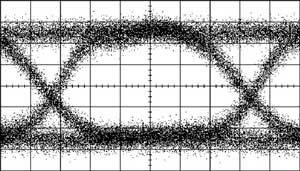
Bandwidth Eye diagram
This type of testing will provide specifications for the
datalink as to the types of fiber required and the loss
budget of the link. It is those specifications that will
determine the use of the datalink in a communications
system design and what performance parameters will need
testing after installation.
Installed Datalink
Testing
Testing
installed datalinks includes testing the cable plant
first then testing the operation of the datalink
transceivers over the cable plant. The cable plant will
be tested after installation to ensure the installation
was done properly before the communications system is
installed and tested.
Multimode cable plants are rarely tested for bandwidth
but require testing for optical loss (called insertion
loss.)
Short singlemode cable plants are also tested for loss
only, but long distance high bitrate singlemode systems
may also require testing the cable plant for bandwidth,
e.g. chromatic dispersion and polarization mode
dispersion. Short links may also have problems with
reflectance from connectors, so special non-reflective
APC style connectors are usually specified since
reflectance testing can be difficult.
Testing the operation of the transceivers with the cable
plant includes optical power testing of the output of
the transmitter and the receiver input power compared to
specifications for the link.
Power
testing of datalink.
After the datalink or communications system is
installed, testing the BER or SNR of the complete
communications link may be done to confirm that the link
is operating properly.
FOA
Standards for testing cable plant loss and optical
power can be used to properly specify test
requirements.
Test Your Comprehension
After you study this page and "More
on fiber optic transceivers and their components" you
should test your comprehension here.
Table
of Contents: The FOA Reference Guide To Fiber Optics
