DAS -
Distributed Antenna Systems
Wireless traffic is growing at a phenomenal rate. AT&T
says their cellular data traffic grew 80,000% (that's 800
times) between 2007 (the introduction of the iPhone) and
2017. The landscape is covered with cellular towers but
the majority of cellular connections (70-80% for both
voice or data) originate inside buildings, so wireless
coverage inside buildings has become more important.
Cellular wireless signals often cannot penetrate walls and
even windows in large buildings, requiring low-power
cellular antennas placed inside buildings to provide
reliable service. There
are several other reasons for cellular systems inside
buildings or structures. Sometimes the number of users
inside a building like a convention center or sports
facility exceeds the bandwidth of a single cellular
system. In many areas, local laws specify the need for
public safety radio signal coverage (fire, police,
emergency) inside every building that requires indoor
antenna coverage.
And auto or mass transit tunnels are also obvious
applications for cellular antenna systems.
Levi's Stadium for the
San Francisco 49ers has over 700 DAS antennas to serve
70,000 people.
DAS -
distributed antenna system - is a single facility system
usually in a large building, sports facility or other
places where cell signals cannot penetrate like tunnels
for cars or mass transit. Where
systems for public safety are specified in local codes,
they may be referred to a "Radio Enhancement Systems" or
RES. (Here is an excellent reference
on RES from NTIA that also discusses the issues of
radio propagation inside buildings.)
A smaller DAS may pick up cell signals from an outdoor
antenna to connect indoor antennas to the cellular systems
of various carriers through a network of coax cables and
amplifiers. That might work for small systems, but not for
systems with large numbers of users. These systems
generally connect to fiber backhaul like a cell tower and
distribute signals inside the facility digitally over
fiber.
A DAS may be "carrier-owned" where the system sometimes
only handles the carrier that owns the system but may
handle other providers, or "neutral-host" where one
private system handles multiple carriers and sometimes
other systems, e.g. WiFi.
Equipment, labor, and maintenance costs for deploying
in-building systems can be expensive and wireless
providers find it difficult to justify the ROI for such
systems except for the very top tier venues. By utilizing
a neutral host model, multiple carriers share the cost
associated with these installations while improving
subscriber satisfaction and ultimately increasing minutes
of use on their system. Since the cost associated with
providing service to in-building and other underground or
RF
(radio frequency, e.g. wireless) resistant
environments is shared among multiple carriers as well as
the system owner in a neutral Host DAS model, the medium
and smaller venues are becoming economically feasible.
Passive DAS
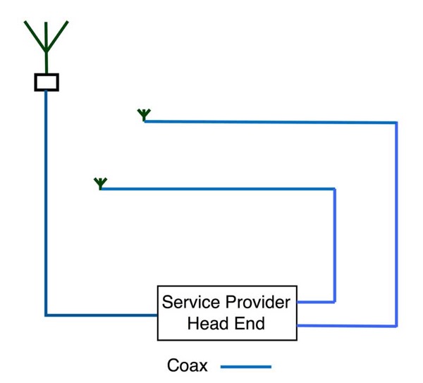
A small "Passive" DAS is simply repeaters for signals
to/from an outside antenna. The electronics amplifies the
signals and connects remote antennas over large
(12-25mm/0.5-1inch) coax cables. Besides the obvious noise
problems with all analog systems, the coax cable runs were
limited to about 100m (330ft) making this a difficult
system to use in large buildings or structures. Passive
systems have been used mainly in small to medium sized
buildings - ~10,000-200,000 sq ft size - and are being
replaced by active digital systems.
Active or Digital DAS
This modern solution distributes the signal inside the
building or facility over fiber as digital signals.
Although there have been some systems that use RF over
fiber inside the building, it’s not common anymore. A DAS
has to connect to service providers which is done with
fiber backhaul to all the service providers for large
facilities and may be done by wireless antennas on the
building for smaller facilities. Fiber backhaul enhances
service by providing greater capacity and simplifies
installation since coax cabling to the carrier antenna is
not necessary.
Digital signals over fiber for a DAS inside a
facility generally use one of two standards - CPRI or
OBSAI.
Many systems use CPRI - The Common Public Radio Interface
–to connect the BBU and RRU. CPRI is an industry
cooperation aimed at defining a publicly available
specification for the key internal interface of radio base
stations between the Radio Equipment Control (REC) and the
Radio Equipment (RE). The parties cooperating to define
the specification are Ericsson AB, Huawei Technologies Co.
Ltd, NEC Corporation, Alcatel Lucent and Nokia Siemens
Networks GmbH & Co. KG.
Open Base Station Architecture Initiative (OBSAI) was a
trade association created by Hyundai, LG Electronics,
Nokia, Samsung and ZTE in September 2002 with the aim of
creating an open market for cellular network base
stations. The hope was that an open market would reduce
the development effort and costs traditionally associated
with creating base station products.
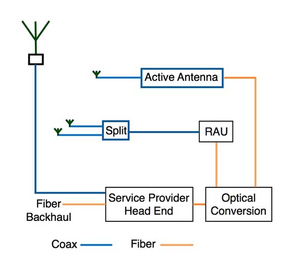
The block diagram here is generic – there are currently no
widely-accepted standards - practically every
manufacturer of DAS systems has different names for the
various operational blocks and even some unique
architectures, for example using PONs (passive optical
networks) like OLANs and FTTH. But the idea is to get
wireless signals to numerous remote antennas over fiber.
Some systems convert to coax at remote antenna units (RAU)
and then distribute to numerous low-power antennas, often
multiples through coax splitters, covering small areas.
Other systems use active antennas that only require a
fiber connection and power, the electronics are built into
the antenna like the new small cell antennas.
Active DAS systems are used in larger buildings, up to
1milion sq ft.
DAS Cabling
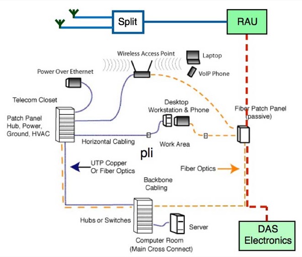
The
architecture of DAS cabling is not much different from
an Ethernet LAN or standardized
structured cabling and most systems operate on
singlemode fiber. In some cases, DAS systems can be
monitored by network management software used for LANs.
DAS and WiFi networks are both usually included in an
installation since both serve similar purposes.
Smartphones will generally choose to operate over WiFi
networks for data when WiFi has more available
bandwidth.
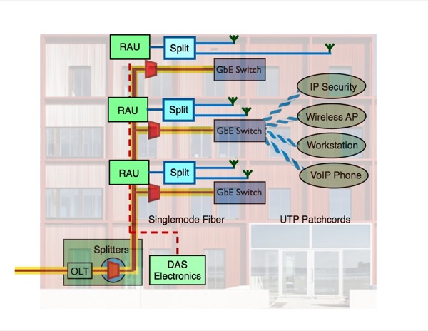
DAS is also compatible with a passive OLAN
system since both use SM fiber and similar backbone
cabling architecture.
There are no "standards" for DAS design, although some
organizations which develop structured cabling standards
are attempting to develop either standards or
guidelines. The problem is the variety of systems and
components that are very different from Ethernet LAN
components, for example, where all components are
essentially identical in function and interoperable. In
a DAS, various manufacturers may use components and
layouts that are different enough that a standardized
cabling system would not be able to accommodate them and
the variations in buildings make antenna location
somewhat unpredictable. A standardized design for a new
building might put antennas on a grid for convenience in
installing cabling, but the antennas in the actual
building may not provide adequate coverage. This a DAS
will be a custom design with optimized architecture
based on site testing, not something designed around
some simplistic cabling guidelines, but will use the
typical components (mainly singlemode fiber) of the
structured cabling standards.
DAS Design
DAS design is typical of wireless networks. Wireless
networks depend on proper positioning of antennas and
access points to get proper coverage for users. The
locations of antennas will be determined by a site survey
using RF test equipment similar to the site survey done
for WiFi. RF signals are hard to predict inside buildings
as different building materials and layouts will affect
signal coverage, so site testing is important.
Various vendors have different equipment available,
including different architectures and even power levels.
The lack of standardization in the equipment means that
cable plant design must follow the choice of equipment
vendors. The
total number of antennas and placements will require a
comprehensive analysis, but one guideline seems to be one
antenna for ~100 users and perhaps 1-2 antennas per floor
of a building.
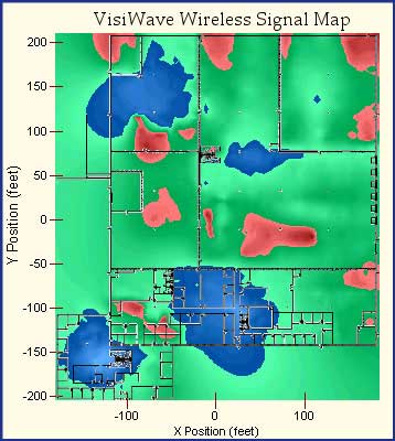
Wireless site survey for
office building
Outdoor
locations may require antenna designs to be camouflaged
for architectural reasons, for example on historic
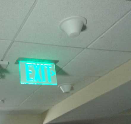
buildings or neighborhoods. Indoors the antennas are
usually placed on the ceiling. There are even antennas
that can clamp on railings in large venues like sports
facilities.
DAS antennas in a sports
facility
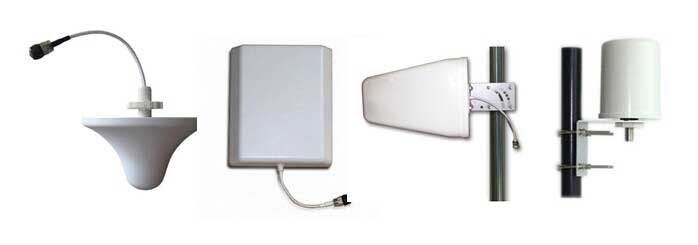
Different types of DAS antennas (ZDA Comm.)
RAUs are usually
placed inside of existing telecom rooms. Indoor mini
antennas (the size of smoke alarm) could be placed in
boxes and other interior areas or placed within dropped
ceilings. Since RAUs are relatively small, the space and
power requirements may be accommodated by current telecom
room design. Connection from RAUs to antennas is generally
on coax so placing coax must be included in designs.
Entrance
facilities have special requirements. Neutral host systems
will have to accommodate 4 or more service providers so
entrance facilities must be designed to allow adequate
entrance conduits and space for equipment. AT&T has
recommended approximately 10’ x 30’ area (~3 X 10m),
inside or outside for AT&T freestanding facility for
equipment location (“head end room”) for their equipment
in a medium-large facility, additional space may be
required to accommodate equipment from the other wireless
carriers. AT&T also recommends 200A service for the
head end.
DAS Installation
DAS systems are sometimes all indoors, like in a
convention center, or outdoors like a sports stadium, or a
combination of both, like a college campus. The type of
location will determine the types of components and
installation techniques necessary. A modern DAS system
will use fiber to connect the head-end to the RAUs and
coax to the antennas. Installers should be familiar with
both fiber and coax installation and testing. Besides the
head end, RAUs like WiFi access points will also require
power, another consideration in the design.
Installation follows normal procedures for premises or OSP
fiber optic cables. If useful fibers are available in
current cable plant, one can patch in the equipment. If
new cables are needed, follow usual installation
guidelines. Field terminations should use spliced on
pigtails or prepolished splice connectors (field
polishing of singlemode terminations is discouraged
due to the difficulty of controlling reflectance.) If
small fiber counts are needed, it’s possible to use prefab
assemblies where the installation is simple but care must
be given to cleaning and inspecting every connection.
With short
SM links, loss should not be a problem but reflectance can
cause transmission problems.
Every
installation program should include testing cables for
insertion loss with a light source and power meter. This
test works just like the communication system works with a
source (transmitter) at one end and a meter (receiver) on
the other end. If properly done, an insertion loss test is
the most valid way to evaluate a cable plant for use with
a typical communications system, but higher speed systems
require additional tests to find problems like reflectance
or dispersion. OTDR testing may be used for
troubleshooting if a high resolution OTDR is available
that can resolve the short cables typical of a DAS system.
Testing the short cables for DAS is similar to the testing
issues for FTTA (fiber to the antenna) so we recommend you
read the page on
testing FTTA.
Dirt is the #1 enemy of fiber optic connectors because it
can cause loss and reflectance, even damage connectors.
Inspect every connector before you make a connection with
it. Check the connector and the receptacle it will be
plugged into as either or both may be dirty.
More
on wireless in premises systems including wireless
network standards .
More On Fiber For
Wireless
FTTA- Fiber To The
Antenna
Testing FTTA
Fiber
DAS - Distributed
Antenna Systems
Small Cells
WiFi
- Premises Wireless
Comparing
WiFi, Small Cells and DAS.
FOA
Guide Table of Contents.
|