|
Connector
and Splice Loss Testing
Note:
In
fiber optics, a single connector has no loss. The
"loss of a connector"
is defined as a "connection loss" caused by a mated
pair of connectors.
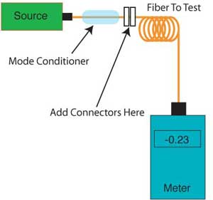
The lab method used to establish the average loss
value of a connector
design is shown below. The loss of connectors on a
patchcord or short
cable is given by FOTP-171 and the loss of an
installed cable
plant is measured by OFSTP-14 (MM) or OFSTP-7 (SM.)
In
order to establish a typical loss for connectors, it is
necessary to test all connectors in a standardized
fashion.
Measurements of
connector or splice losses are performed by measuring
the transmitted
power of a short length of cable and then inserting a
connector
pair or splice into the fiber and measuring the change
of loss as a
result of adding a connection. This test ( designated
FOTP-34
by the TIA) can be used for both multimode and
singlemode fiber,
but the results for multimode fiber are very dependent
on mode
power distribution.
FOTP-34
has three options in modal distribution: 1)EMD
(equilibrium
modal distribution or steady state) , 2) fully filled,
and 3) any
other conditions as long as they are specified. Besides
mode power
distribution factors, the uncertainty of the measured
loss is
a combination of , inherent fiber geometry variations,
installed
connector or splice characteristics, and the effects of
the splice bushing
used to align the two connectors.
This
test is repeated hundreds or thousands of times by each
connector or splice manufacturer, to produce data that
shows the repeatability
of their connector design, a critical factor in figuring
margins
for installations using many connectors. Thus loss is
not the
only criteria for a good connector, it must be
repeatable, so
its average loss can be used for these margin
calculations with
some degree of confidence.
Connector
and Splice Durability
Another
factor important to a connector is the durability of
the design, shown by its ability to withstand many
matings without
degradation in loss. Testing connector durability is
simply a
matter of repeated mating and demating of a connector
pair while
measuring loss. Since the loss is a function of both
connectors
and alignment sleeve, it is helpful to determine which
are the
contributors to degradation. Plastic alignment sleeves,
when used
with ceramic connectors, for example,will usually wear
out much
faster, shaving plastic off onto the connector ferrules
and causing
increased loss and return loss. When testing durability,
periodic
inspection of the connector end faces and ferrules with
a microscope
to determine wear or contamination is very important.
Splice
durability is one of withstanding many cycles of
environmental
stress, since splices are often used in splice
enclosures in pedestals
or mounted on poles where they are exposed to the
extremes of
climatic changes. Manufacturers usually test a number of
splices
through many environmental cycles and accelerated aging
to determine
their durability. Such tests may take years.
Connector
Reflectance
If
you have ever looked at a fiber optic connector on an
OTDR,
you are familiar with the characteristic spike that
shows where
the connector is. That spike is a measure of the
reflectance
(sometimes also called optical return loss) of the
connector, the names used for the amount of light
that is reflected back up the fiber by light reflections
off the
interface of the polished end surface of the connector
and air.
It is also called fresnel reflection and is caused by
the light going
through the change in index of refraction at the
interface between
the fiber (n=1.5) and air (n=1).
That
return spike is one component of
the connector's loss, representing about 0.3 dB loss for
a non-contact or air-gap connector (two air/glass
interfaces at 4% reflection each), the minimum loss for
non-contacting
connectors without an index-matching fluid. But in
high-bit rate
singlemode systems, that reflection can be a major
source of bit-error
rate problems. In some singlemode systems, the reflected
light interferes with the laser diode transmitter,
causes mode-hopping and can be a source of noise.
Minimizing
the light reflected back into the laser is necessary to
get maximum
performance out of high bit rate laser systems,
especially the
AM modulated CATV systems. In multimode systems,
reflections can add to background noise in the
fiber.
Since
this is more a problem with singlemode systems,
manufacturers
have concentrated on solving the problem for their
singlemode
components but multimode connectors benefit also.
Several schemes have
been used to reduce reflectance, mainly reducing the gap
between
connectors to a few wavelengths
of light using a physical contact (PC) polish on the end
of the
connector ferrule, which reduces the fresnel reflection.
The usual
technique
involves polishing the end surface of the fiber to a
convex surface
or at a slight angle to prevent direct back reflections.
Another, even more effective solution, is to
polish the end of the singlemode
connector ferrule at a small angle (about 8 degrees) to
cause any
reflected light to be absorbed in the fiber cladding.
These are
called angle-polish connectors (APC) and are widely used
for CATV and
high big rate digital systems.
More
on different methods of reflectance testing.
|
