|
Introduction
The
end
user, who owns and uses communications systems, often finds it
hard to
get information about fiber optics aimed specifically at them.
Industry
standards are written by and for manufacturers. Most training
material
is written to train installation techs, the group the FOA
focuses on
with most of its certification programs.
So the
FOA has created a special section of our website where end
users can
find answers to their questions on fiber optics or even find
out what
questions to ask. We think you will find this interesting and
useful.
We welcome your questions and feedback.
|
Getting
Started
In Fiber Optics
The FOA has several options to help you get started in fiber
optics. These are the way to get started.
Fiber
U -
FOA's free online training program
FOA
Online Tutorial on Fiber
Optics
Lennie
Lightwave's Guide To
Fiber Optics
Self-Study
Guide To Fiber Optics
|
- For
Potential Users Of Fiber Optic Communications:
- Should
you
use fiber optics for your communications system?
- What
are
its advantages and disadvantages?
- Isn't
fiber
optics still too new for everybody to adopt it?
- Is
it
hard to design and install fiber optic networks?
- Do
they
require maintenance?
-
- This
short
guide is designed to help answer those questions for users
pondering the choices and/or planning an installation and
provide links
to more in-depth information.
This guide covers all applications of fiber optics.
If your applications are primarily premises cabling, the FOA
has a
section of its FOA Online
Reference Guide that focuses on fiber, copper and
wireless for premises
applications. and another focusing on outside
plant fiber optics.
If you are new to fiber optic communications, the FOA Guide To Fiber Broadband
book can help you understand how fiber optics is the backbone of the
world's communications systems - landline, submarine and wireless. The book is available on Amazon.
|
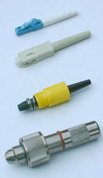 Fiber
optic connectors from the 1970s , 1980s, 1990s, 2000s (bottom
to
top)
Fiber
optic connectors from the 1970s , 1980s, 1990s, 2000s (bottom
to
top)
|
- 1. Introduction
One often sees articles written about fiber optic
communications
networks that implies that fiber optics is "new." That is
hardly the
case. The first fiber optic link was installed in Chicago in
1976. By
1980, commercial long distance links were in use and fiber
optic data
links for computers were available. Since that beginning, fiber
has become
very commonplace - one should say dominant - in the
communications
infrastructure.
The Internet is 100% fiber optics. On land and
under the oceans, fiber optic cables are connecting users to data
centers around the world on fiber. Even inside the data centers,
communications is virtually all on fiber.
- If
you make a long distance call today, you are
undoubtedly
talking on
fiber optics, since it has replaced copper or
microwaves in virtually all the circuits
for long distance communications; only a few
subscriber lines are copper and even cell towers are connected on fiber.
Most large office
buildings have
fiber in the building itself. Only the last link to
the
home, office
and phone are not fiber and installations of fiber
to the
home are
growing rapidly.
CATV also discovered fiber optics, along with compressed
digital
video back in the 1990s. CATV systems have been converted to
fiber optic
backbones which allow voice and data transmission usig cable modems in
addition to video.
The LAN backbone also has become predominately
fiber-based.
The
back-end of mainframes and storage area networks
(SANs) are
almost
totally fiber. Only the desktop is a holdout, a
variety of copper and fiber used for desktop computers and WiFi for
mobile devices.
Fiber optics offers an unrivaled level of security. It
cannot be easily
jammed or tapped and is immune to interference. It is widely
used for
security cameras, perimeter alarms and other critical
systems in
military, government, utility and civilian applications.
Fiber optics really is the medium of choice for long
distance, high
bandwidth or secure communications. Lets look at why it is,
how to
evaluate the economics of copper versus fiber and how to
design fiber
networks with the best availability of options for
upgradeability in
the future. -
- 1.1
Its really all a matter of economics
Fiber optics has become widely used in telecommunications
because of
its enormous bandwidth and distance advantages over copper
wires or wireless.
Commercial systems today carry more phone conversations over
a pair of
fibers than could be carried over thousands of copper pairs
and can be
run hundreds or even thousands of kilometers between all-optical repeaters.
Material
costs, installation and splicing labor and reliability are
all in
fiber's favor, not to mention space considerations.
In CATV, fiber pays for itself in enhanced reliability and
the ability
to offer enhanced services. The enormous number of repeaters
that were once used in a
broadcast cable networks on coax cable were a big source of failure. CATV
systems' tree
and branch architecture means and upstream failure causes
failure for
all downstream users. Reliability is a big issue, since
viewers are a
vocal lot if programming is interrupted! The ability to
offer Internet
access using cable modems has created significant revenue streams for CATV
operators also.
For LAN and other datacom applications, the economics are
less clear
today, especially since most connections are on WiFi for mobile devices. As distances go over 50 to 100
meters and
speeds above 1 Gb/s, fiber is the best choice.
- Some
applications demand fiber. Factory floors are messy
electrical
environments where optical fiber, both glass and plastic,
are used
everywhere to provide reliable communications. Long CCTV
links in
security systems are now almost exclusively fiber. Even
millions of
cars use fiber (POF) for safety and
entertainment/communications
systems. If reliable communications are a must, fiber is
usually the
best choice.
-
- 1.2.
Technology often says go fiber
Fiber's advantages over copper result from the physics of
transmitting
with photons instead of electrons. In glass, optical
attenuation is
much less than the attenuation of electrical signals in
copper and much
less dependent on signal frequency. We all know that fiber
optic
transmission neither radiates RFI nor is susceptible to
interference,
making it the only choice for secure communications. Unlike
copper
wires that radiate signals capable of interfering with other
electronic
equipment, fiber is totally benign. Utility companies even
run power
lines with fibers imbedded in the wires for both
communications and
network management! The bandwidth/distance issue is what usually convinces the
user to
switch to fiber.
Where wireless is used is for mobile devices
connected on WiFi or cellular systems. Both generally depend on fiber
backbones for connectivity since wireless is not wireless except in the
final connection from antenna to the user's device.
-
- Read
more on fiber
vs
copper generally and in LANs or wireless in premises cabling systems.
Here is more information on fiber optics in the worldwide communications systems.
|
Learn
More
Here are some advanced ways to learn more about fiber
optics:
Fiber
U -
FOA's free online training program
FOA Guide To Fiber Optics
Freqently
Asked Questions (FAQs)
FOA Tech
Bulletins
|
- 2. Understanding Fiber
Optic Communications
Fiber optic data links are the communications pathways between
devices. A
link is bidirectional, usually with signals transmitted in
two
directions on two different fibers. Using two fibers is
usually the
cheapest way, since the optical fiber itself is now about as
cheap as
kite string and fishing line! FTTH PONs - fiber to the home passive optical networks - use one
fiber in two
directions so it can use one PON coupler transmitting and
receiving for
lower system cost.
- The link connects electronic signals
from two
devices that need to communicate, just like a copper cable.
The link
has a transmitter that converts electronic signals from
communications
equipment to optics and a receiver that converts the signal
back to
electronics at the other end.
-

-
- Fiber
optic transceivers use LEDs or semiconductor lasers to
convert
electronic signals to optical signals. LEDs, similar to
those used
everywhere for indicators, except transmitting in the
infrared region
beyond human perception are used for slower links, up to
about 100
million bits per second (Mb/s), for example fast Ethernet
LANs. Faster
links use infrared semiconductor lasers because they have
more
bandwidth, up to tens of billions of bits per second (Gb/s).
Lasers
have more power, so they can also go longer lengths, as in
outside
plant applications such as long distance telecom or CATV.
As noted, transmitters use infrared light. Infrared light
has lower
loss in the fiber, allowing longer cable runs. Typically
multimode
glass fibers use light at 850 nm, referred to as "short
wavelength" and
singlemode fiber operates at 1310, 1470 or 1550 nm, called
"long
wavelength."
Safety Note: Since the light being transmitted through the optical fiber
is beyond
the range of human sight, you cannot look at the end of a
fiber and
tell if light is present. In fact, since some links carry
high power,
looking at the end of the fiber, especially with a
microscope which
concentrates all the light into the eye, can be dangerous.
Before
examining a fiber visually, always check with a power meter
to insure
no light is present unless you know the far end of the fiber
is
disconnected and use a microscope equipped with a laser
filter.
At the receiver end, a photodiode converts light into
electrical
current. Photodiodes must be matched to the transmitter
type,
wavelength, power level and bit rate as well as the fiber
size to
optimize performance. It's the receiver that ultimately
determines the
performance of the link, as it needs adequate power to
receive data
reliably. Receivers have a certain amount of internal noise
which can
interfere with reception if the signal is low, so the power
of the
optical signal at the receiver must be at a minimal level.
The power at the receiver is determined by the amount of
light coupled
into the fiber by the transmitter diminished by the loss in
the fiber
optic cable plant. The installer will test the cable plant
for loss
after construction, comparing it to a loss calculated from
typical
component values called the "loss budget." Transmitter power
can be
measured when the networking equipment is installed using a
patchcord
attached to the transmitter.
Networks adapt the generic fiber optic link described above
to a
specific network's needs. An Ethernet link will be optimized
for the
bitrate and protocol of the version of Ethernet to be used,
for example
Gigabit Ethernet. Video links may be analog or digital,
depending on
the camera, and may include camera controls in one direction
and video
in the other. Industrial links may be based on RS-232 or
RS-422
protocols.
Most computer or telecommunications networks have adopted
standards for
fiber optic transmission as well as copper wiring and
wireless.
However, sometimes the user has equipment with copper
interfaces but
wants to use fiber. Then they can use fiber optic media
converters,
which do exactly what their name suggests. Media converters
will
convert from one media to another, typically UTP copper to
optical
fiber, coax to optical fiber or multimode to singlemode
fiber. Media
converters are like transmitters and receivers in that they
must be
specified for specific network applications to insure the
proper
operation in that application.
Since so many link types exist, it is impossible to
generalize on fiber
optic link characteristics, but there
is a
table in the FOA website detailing most standard networks.
When designing or installing fiber optic cabling, the
contractor can
either design to cabling standards, which allows use with
any network
or communications system designed for those standards, or
for a
specific network, which may allow optimizing the cable
plant. If the
actual network to use the fiber optic cabling is not known,
the best
plan is to design, install and the test cable plant based on
standardized
fiber
optic component specifications rather than any
specific
network needs.
|
|
References
Whatever you want to know about
fiber, you can probably find it on
The FOA
Online Reference Guide To Fiber Optics
The
FOA Reference Guide To Fiber Optics (print version)
The
FOA Reference Guide to Premises Cabling (print version)
The
FOA Reference Guide To Outside Plant Fiber Optics (print
version)
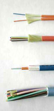
- Typical
indoor fiber optic cables:
- zipcord,
distribution, loose tube and breakout (from top)
-
-
-
-
-
-
-
-
-
-
-
-
-
-
-
-
-
-
-
-
-
-
|
3.
Checklist For Users Of Fiber Optic Communications Products
This is intended as an overview and installation checklist for
all
managers and engineers on the overall process of designing,
installing
and operating a fiber optic communications system. Fiber
optics offers
major advantages for communications systems including
security,
distance and bandwidth. Proper application of fiber optic
technology
will lead to highly reliable systems. But the user must choose
the
proper products, design and install an appropriate cable
plant, and
make sure components are tested, all following appropriate
industry
standards. This guide is designed to provide the information
necessary
to ensure proper installation and usage of fiber optic
systems. As
references, we will use:
The
FOA Online Reference Guide To Fiber Optics
The
FOA Reference Guide To Fiber Optics (print version)
The FOA Reference Guide to Premises
Cabling (print version)
The FOA Reference Guide To Fiber Optic Network Design
The NECA/FOA 301 Fiber Optic Installation Standard
Note
that these documents refer to other more detailed
documents such as TIA or ISO standards.
While
this document is primarily focused on the design,
installation and
maintenance of fiber optic cable plants, most end users will
be
interested in costs, so the FOA has a separate document on estimation.
3.1.
Overview of Fiber Optic Network Design and Installation
(Download
the comprehensive FOA Tech Bulletin on Designing
Fiber
Optic Networks. PDF 1.3 MB) or get a copy of the The FOA Reference Guide To Fiber Optic Network Design
3.1.1.
Select a communications system, link, module or converter that fits the data
format
you plan to transmit.
The first step is to choose the type of system needed. Fiber
optic
communications products exist for almost every type of
communications
system, from high speed telephone and CATV systems to simple
low speed
RS-232 or relay closure links. Many are media converters from
standard
electrical interfaces like Ethernet that have various options
on data
rates. Some are proprietary links for specialty equipment used
for
utility monitoring, industrial control, video surveillance,
etc.
3.1.2.
Select a fiber optic product that is specified to work over
the range
of your application. Note the type of fiber and other
components such
as connectors required for this product.
a. Consider the range of the link as that affects the type of
fiber and
transceivers needed.
b. Short links use multimode fiber and LED sources, while
longer links
use lasers and singlemode fibers.
c. Most fiber optic communications products offer several
versions that
cover different ranges.
d. Alternately, if you already have fiber optic cable plant
installed,
select a product that will operate over your fiber optic cable
plant,
considering both fiber type and distance.
3.1.3.
Select a fiber optic cable type appropriate for the
application.
a. Determine the working environment of the fiber optic cable
plant.
Some applications are in office environments, some on factory
floors,
above ceilings and some are outdoors.
b. Outdoors, some cables are installed aerially, either lashed
to a
messenger or self-supporting, some are buried directly or in
conduit
and some must run under water.
c. All outdoor cables require protection from water entry and
any other
environmental factors particular to the installation.
d. Each application puts requirements on the cable design that
should
be discussed with cable manufacturers who can recommend cable
types
appropriate for that application.
e. Not all manufacturers make the same type of cable, so
talking to
several vendors may provide options in cables that affect
price or
performance.
f. Consider installing several extra fibers in case any are
damaged in
installation or if additional fibers are needed for future
expansion.
(In fact, for critical applications, it may be advisable to
install a
complete backup link and/or redundant fiber optic cable plant
run in a
different route.)
g. Often singlemode fibers are added to multimode cables
(called a
hybrid cable) in case future networks need higher bandwidth.
h. At this stage, also decide on the installation hardware
needed, such
as conduit or innerduct for buried cables and hangers or
lashing for
aerial cables.
3.1.4.
Plan ahead on splicing requirements.
a. Long lengths of cables may need to be spliced, as fiber
optic cable
is rarely made in lengths longer than several kilometers due
to weight
and pulling friction considerations.
b. If fibers need splicing, determine how to splice the fibers
(fusion
or mechanical) and what kind of hardware like splice closures
are
appropriate for the application.
3.1.5.
Choose connectors of a style and termination type
appropriately for the
application.
a. Cables will need terminations to interface with the
communications
products.
b. Connectors need to be chosen appropriately or patchcords
with one
end terminated with connectors compatible with the
communications
products will be needed.
c. Fiber optic connectors have several termination methods,
some using
adhesives and polishing, some using splicing, which have
tradeoffs in
performance.
d. Discuss connectors with both manufacturers and installers
before
making this choice.
3.1.6.
Ensure the calculated link loss is substantially less than the
link
margin of the communications products.
a. Calculate the power/loss
budget for the link.
b. Using typical component specifications and the design of
the cable
plant (type of fiber, length, transceiver wavelength, number
of
connectors and splices) you can calculate the approximate
optical
loss of the cable plant
c. Compare it to the link margin for the communications
products you
have chosen.
d. Discuss potential margin problems with communications
equipment
vendors.
3.2.
Install the cable plant.
a. Using the design developed in this process, install the
cable plant.
b. Some users learn to install and maintain the fiber optic
cable plant
themselves, while others use contractors.
c. Installers or contractors should be trained and experienced
in the
installation type being done, have references for previous
work and be certified
by independent organizations like The Fiber Optic Association.
d. Follow the guidelines in the NECA 301-2004 Standard For
Installing
and Testing Fiber Optic Cables, available from The National
Electrical
Contractors Association.
e. Do not discard excess cable from the installation, but
store it for
future needs in restoration if the cable plant is damaged.
3.3.
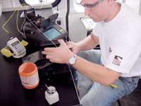
Test the cable plant for end-to-end optical loss.
a. Test
the cable plant for optical loss according to industry
standards. Most cable plants are tested according to standards
TIA/EIA-526-14 for multimode fibers and TIA/EIA-526-7 for
singlemode
fibers using Method B, with a one cable reference for 0dB
loss. Calculate
the
approximate loss expected before you begin testing.
b. Longer cables with splices should also be tested with an
OTDR to
verify splice quality.
c. Cables installed aerially or in areas of likely stress can
also be
tested with the OTDR to verify installation quality.
d. Troubleshoot
any fibers that are high loss and correct the problem.
3.4.
Install the communications products and test their operation.
a. After the cable plant is tested and known good, install the
fiber
optic communications equipment and test its operation.
b. Use any self-testing options to check operation, use BERT
(bit-error
rate test) equipment or transmit known data and look for
errors.
c. Once a network is operating properly, it should require no
maintenance in fact, attempted maintenance on premises
systems by
un-qualified personnel is often a cause of damage so it is
best to
lock fiber optic component enclosures to reduce unauthorized
entry - a
requirement for class 4 (high power)lasers.
d. Outside plant networks may need frequent visual inspection
just to
find damage or potential damage.
3.5.
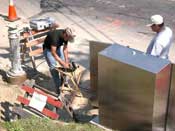
Document the fiber optic network.
a. Perhaps the most important part of any installation is the
final
documentation.
b. Accurate and complete documentation is invaluable in
upgrading,
troubleshooting or restoring a network. (Download the FOA Tech
Bulleting "Fiber
Optic
Restoration" PDF, 90 kB) Documentation should include
identification of all components, the paths of each cable,
types of
cable (and where the excess is stored for restoration), cable
section
lengths, locations of splices or terminations and the optical
loss of
each fiber measured at installation.
c. If OTDR traces are taken, those should be stored with the
documentation.
d. Copies of all documentation should be kept at each end of
the link
and backups stored in a safe place.
|

Documentation
begins with a good blueprint.
|
- 4.
Important Considerations in Fiber Optic Installation
Fiber optics offers major advantages for communications
systems
including security, distance and bandwidth. Proper
application of fiber
optic technology will lead to highly reliable systems. That
means the
user must install an appropriate cable plant and test every
component,
all following appropriate industry standards. This guide is
designed to
provide to those directly involved in planning and
installing the fiber
optic network the information necessary to ensure proper
installation
and usage of fiber optic systems.
-
- Notes:
- Every project needs "paperwork" to define the
project for both the user and the contractor. See the FOA
page on Paperwork for a rundown of the important
documents and what they mean.
- This list only concerns
itself with the project steps unique to fiber
optic systems, but many OSP applications require obtaining
permits,
easements or rights-of-way. That is beyond the scope of
this document!
-
- 4.1.
Do a complete design before beginning cable plant
installation. (FOTN,
Chapter 9 and NECA-301)
a. Establish criteria for the install, based on the
communications
paths required
b. Know how many fibers of what types are needed add
extras for
repairs or growth
c. Determine hardware requirements: connectors, splices,
patch panels,
closures, etc.
d. Plot the cable route and determine cable lengths
e. Show how installed (premises, buried, conduit, innerduct,
underwater, pole locations for aerial, etc.)
f. Mark termination and splice points
g. Attach data from link loss budget and use it as a guide
for testing
h. Don't try to build a marginal design allow for
"Murphy's Law"
i. Follow the NECA 301-2004 Standard For Installing and
Testing Fiber
Optic Cables in design and installation
j. At the same time, design the facilities for the
communications
equipment, including locations, allowing for adequate
spaces, power and
grounding and HVAC as needed
k. Make complete lists of what components and hardware are
needed and
where they are to be used
-
- 4.2.
Work with vendors on component specs to get best quality and
price.
a. Vendors usually have suggestions on components like
cables or
hardware that can facilitate design and implementation, but
always get
several opinions and compare their suggestions to what you
understand
you need .
b. Consider options like pre-terminated cables or air-blown
fiber for
short indoor cable runs
c. Remember to plan for purchasing overages on components to
cover
extra cable for restoration or extra connectors necessary
due to yields
in termination
d. Be careful of industry or manufacturer "jargon" as not
everyone uses
the same term in fiber optics
- e.
Once you have a design and component pricing, you can do a
complete project
cost
estimate.
-
- 4.3.
Have all components available before beginning installation
so crews
may complete the installation promptly and properly.
a. Inventory everything received
b. Check for shipping damage
c. Store in a safe, dry place until used
d. Separate as needed for each work site
e. While at the job site, consider using guards if
components are left
onsite overnight
-
- 4.4.
Use only trained, qualified installers, preferably
FOA-certified.
a. Installing fiber optics is not difficult, but has special
issues
familiar to those with experience
b. Make sure the installers are experienced in the type of
installation
you are planning, as installers often specialize in aerial,
underwater,
or even singlemode installation
c. Look for FOA
CFOT certification (www.thefoa.org) and good
references from
similar installations
d. Review the design with the installer to familiarize them
with the
job and see if they have advice on how to make it easier or
better but
use your judgement regarding any changes suggested.
-
- 4.5.
Review safety
issues and establish rules for the installation.
a. All installers and supervisors should be briefed on
safety rules
b. Ensure that you have copies of the documentation
regarding your
contractors bonding, insurance, workers compensation, OSHA
certificates
etc.
c. Use NECA/FOA 301 Standard, Section 3 plus any applicable
OSHA or
other regulations
-
- 4.6.
Install the cable plant.
a. NECA/FOA 301, Section 5.4 offers good guidelines for
installation
b. Watch for proper handling to prevent cable damage,
especially cable
tension and bend radius
c. Long lengths (>200m) can be tested by an experienced
technician with an OTDR after installation but before
splicing or
termination if there is any question about potential damage
during
installation. Remember OTDR testing is optional, but every
link
requires insertion loss testing with a meter and source.
d. Install the hardware: NECA 301, Section 5.5
e. Splice as needed: NECA 301, Section 6.3, generally use
fusion
splicing in outside plant and singlemode applications,
mechanical
splices limited to premises multimode cables
f. Terminate ends: NECA 301, Section 6.2, generally
multimode
connectors will be installed on the cables directly while
singlemode
connectors will use pre-terminated pigtails to reduce loss
and back
reflection which are both important to laser transceivers
used with
singlemode fiber, especially in short links (~<2 km)
g. All splices and terminations should be placed in
appropriate
hardware for protection
h. Remember to clean
all
connectors properly and keep dust caps on all
connectors
i. All fiber optic cables should be color-coded by jacket
colors
and/or marked with orange or yellow tags or whatever color
is
designated for your cable plant to identify it as fiber
optic cable.
j. Carefully mark all cables and connections for
identification in a
manner consistent with the company documentation processes.
k. Dust caps from the connectors and couplings terminated in
the
enclosure belong to that enclosure and should be put in a
small plastic
bag and taped inside the cabinet for future use.
-
- 4.7.
Test and troubleshoot the cable plant. (NECA-301,
Sec 7, 4
Ways To Test An Installed Cable Plant) and Troubleshooting
fiber optic
cable plants and communcations systems, Testing
FAQs )
- a.
All cable plants must be tested for insertion
loss per industry standards (TIA/EIA-526-14 for
multimode,
TIA/EIA-526-7 for singlemode fibers) at the wavelength(s) to
be used
with the transmission systems chosen
b. Insertion loss must be less than allowable link loss
margin for the
communications equipment being used on the fibers
c. Longer cable plants, especially singlemode and those
using splices,
should be tested by an experienced technician with an OTDR
to verify
splice loss and confirm the cable was not damaged during
installation (
Understanding
OTDRs
, More
advice on using OTDRs properly.)
d. Remember to clean
all
connectors properly and keep dust caps on all
connectors
e. All test data should be recorded for cable plant
acceptance and
saved for future troubleshooting and restoration
-
- 4.8.
Install the communications systems.
a. Install all the active devices according to
manufacturer's
specifications and test for proper operation
b. If patchcords are used for connecting optical ports to
the cable
plant, use tested patchcords that are known to be in good
condition.
Patchcords must match
the
fiber in the cable plant being tested to prevent
excess
loss.
c. Clean
all connectors after removing dust caps and before
connecting
to transceivers or cable plant connectors
d. Using an optical power meter and good reference test
cable, test
transmitter power levels to ensure it is within
manufacturer's
specifications
e. Using an optical power meter, test receiver power levels
to insure
it is within manufacturer's specifications (you can use
these two
pieces of data to calculate the loss of the cable plant
under actual
use, which should correlate with insertion loss test data
using a test
source
f. If the power exceeds the receiver dynamic range and
overloads it,
reduce the power by using attenuators of a type recommended
by the
equipment manufacturer placed at the receiver, checking with
the
optical power meter to ensure the lower power level is in an
appropriate range
-
- 4.9.
Document the fiber optic network. (NECA-301, Sec 8)
a. Perhaps the most important part of any installation is
the
documentation. Good documentation is invaluable in
upgrading,
troubleshooting or restoring a network
b. Documentation should include:
i. Design data, e.g. CAD drawings and maps
ii. Component types and manufacturers
iii. The paths of each cable
iv. Types of cable (and where the excess is stored for
restoration)
v. Cable section lengths
vi. Locations of splices or terminations
vii. Calculated loss budget
viii. The optical loss of each fiber measured at
installation
ix. Fiber numbers/colors connected to each communications
device,
noting transmitter and receiver orientation
x. Spare fibers available for expansion or use to replaced
damaged
fibers
xi. Types of communications equipment
xii. Wavelength of transmission
xiii. Transmitter and receiver power for each transceiver
(and
attenuator values if used)
xiv. OTDR traces if taken
xv. Name and contact information for installers
c. Copies of the documentation should be kept at each end of
the link
and backups stored in a safe place.
-
- 4.10.
Fiber optic premises networks generally do not require
periodic
maintenance.
a. As long as the network is communicating as expected, no
maintenance
should be required and the network should not be touched
unless
communications equipment is moved, added or changed.
b. Attempts at inspection or maintenance are a major cause
of damage to
cables or connectors and getting dirt into components
c. Hardware should be lockable to prevent unauthorized entry
d. Outdoor installations, being more prone to mechanical and
environmental damage should be visually inspected for damage
as part of
a regularly scheduled preventative maintenance program.
-
-
-
- Ask us questions and
give us your feedback. Contact
the FOA.
- If you are planning a fiber optic
communications
system, download a free copy of the NECA-301
Standard
For Installing And Testing Fiber Optic Cables.
|
|
- References:
- The
Fiber Optic Association, Inc. (FOA), www.thefoa.org
The
FOA Online Reference Guide To Fiber Optics
|
| |
Note: This
information is
provided by The Fiber Optic Association, Inc. as a benefit to
those
interested in designing, manufacturing, selling, installing or
using
fiber optic communications systems or networks. It is intended
to be
used as a overview and guideline and in no way should be
considered to
be complete or comprehensive. These guidelines are strictly
the opinion
of the FOA and the reader is expected to use them as a basis
for
creating their own documentation, specifications, etc. The FOA
assumes
no liability for their use. |
| |
Sign Up For The
FOA
Email Newsletter |
