Fiber Optic Measurement
Units: "dB" and "dBm"
Whenever tests are performed on fiber optic networks, the
results are displayed on a power meter, OLTS or OTDR
readout in units of “dB.” Optical loss is measured in “dB”
which is a relative measurement, while absolute optical
power is measured in “dBm,” which is dB relative to
1mw optical power Loss is a negative number (like –3.2 dB)
while power measurements can be either positive (greater
than the reference) or negative (less than the reference.)
Should a meter be set for dB or dBm?
In the early days of fiber optics, source output power
was usually measured in milliwatts and loss was measured
in dB or deciBels. Over the years, all measurements
migrated to dB for convenience. This was when the
confusion began.
Confused? Many fiber optic techs are too. Let’s see if we
can clear up some of the confusion.
Typical Measurement Values in Fiber Optics
Here are some typical measurements in fiber optics of
optical power and loss. You may want to come back to this
section as you read the explanations of dB and dBm below.
Typical power levels measured by an optical power meter:
Telecom
transmitters: 0 to +10 dBm (1 to 10 milliwatts),
Receivers: -30 dBm (1 microwatt)
DWDM
systems with fiber amplifiers: +10 to +20 dBm (10
to 100 milliwatts), Receivers: -20 to -30 dBm (1-10
microwatt)
Data
links and LANs: 0 to -10 dBm (1
to 10 milliwatts, 850 VCSEL), -10 to -16 dBm
(25 to 100 microwatts, LED), Receivers: -16 to -30 dBm
(1-25 microwatts)
Typical losses of fiber optic components which can be
measured by a light source and power meter (LSPM), OLTS or
OTDR:
Fiber
attenuation: Multimode: 3 dB/km at 850 nm (50% loss of
power per km), 1 dB/km at 1300 nm (21% loss/km),
Singlemode: 0.4 dB/km at 1310 nm (9% loss/km), 0.25
dB/km at 1550 nm (5.5% loss/km)
Connectors:
0.3 - 0.75 dB (7-16%)
Splices:
0.05-0.3 dB (1-7%)
Measuring Power
When we make fiber optic measurements, we are measuring
the power in the light coming out of the end of a fiber.
The measurement may be optical power from a test source, a
transmitter or the input of receiver, measured in dBm,
which is "absolute" power - absolute in that it refers to
power calibrated to a national standard, so two people
testing the same fiber output with different power meters
calibrated to the same standard will measure the same
power level within measurement uncertainty of the meters
calibration. If we are measuring loss, like of a
connection, we measure power before the connection and
after the connection and compare the two measurements to
get a relative measurement of loss in dB.
This page will try to explain this in more detail.
The primary calibration standards we use for power
measurements, maintained by NIST (the US National
Institute of Standards and Technology,) are actually
determined by the heating effect of the power of the light
as it is absorbed in a detector. Every fiber optic power
meter sold is calibrated traceable to the NIST standard in
the US or similar primary standards worldwide so different
meters should measure the same power, within the limits of
calibration uncertainty.
Optical power in fiber optics is similar to the heating
power of a light bulb, just at much lower power levels.
While a light bulb may put out 100 watts, most fiber optic
sources are in the milliwatt range (0.001 watts), so you
won’t feel the power coming out of a fiber and it’s
generally not harmful. (Except for DWDM systems with fiber
amplifiers or lasers used for surgery or welding. DWDM
systems with fiber amplifiers can carry enough power to
pit the fiber end or even ignite cables if a fiber in
cracked!) Remember you can't see this light either because
it is in the infrared wavelengths beyond the sensitivity
of the human eye.
Read more on optical
power measurements.
Understanding dB
In the very early days of fiber optics, source output
power was usually measured in milliwatts and loss was
calculated in dB or deciBels. Over the years, all
measurements migrated to dB for convenience. This was when
the confusion began.
Loss measurements were generally measured in dB since dB
is a ratio of two power levels, one of which is considered
the reference value - that's "0 dB" for loss measurements.
dB is a logarithmic scale (remember “logs” from high
school math?) where each 10 dB represents a ratio of 10
times.
3
dB is a ratio of 2 times the reference power (gain)
-3 dB is a ratio of 1/2 (loss)
10 dB is a ratio of 10 (gain)
-10 dB is a ratio of 1/10 (loss)
20 dB is a ratio of 100 (gain)
-20 dB is a ratio of 1/100 (loss)
30 dB is a ratio of 1000 (gain)
-30 dB is a ratio of 1/1000, (loss), etc.
When
the two powers are equal, dB = 0, a result of the log
scale used in dB but a convenient value that’s easily
remembered.
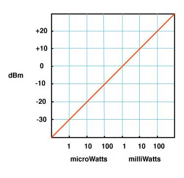
Absolute optical power is measured in dBm or dB referenced
to 1 milliwatt, about the power of a typical laser, and
expressed as dBm. Here is a graph that shows the
relationship of dBm to milliwatts and microwatts.
The actual equation used to calculate dB when the power is
measured in watts is:
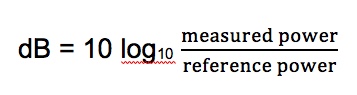
Using this equation, 10 dB is a ratio of 10 times (either
10 times as much or one-tenth as much), 20 dB is a ratio
of 100, 30 dB is a ratio of 1000, etc. When the two
optical powers compared are equal, dB = 0, a result of the
log scale used in dB but a convenient value that’s easily
remembered.
More on dB math below.
In most fiber optic power meters, the readings are in dB,
not watts, so the measurement of dB is expressed more
simply - no logs, just subtraction of two values in dB:
dB = measured power(dB) - reference power (dB)
The
table below shows the ratio of power for dB differences
in power:
|
dB
(gain)
|
Power
ratio
|
dB
(loss)
|
Power
ratio
|
|
0
|
1.000
|
0
|
1.000
|
|
0.1
|
1.023
|
-0.1
|
0.977
|
|
0.2
|
1.047
|
-0.2
|
0.955
|
|
0.3
|
1.072
|
-0.3
|
0.933
|
|
0.4
|
1.096
|
-0.4
|
0.912
|
|
0.5
|
1.122
|
-0.5
|
0.891
|
|
0.6
|
1.148
|
-0.6
|
0.871
|
|
0.7
|
1.175
|
-0.7
|
0.851
|
|
0.8
|
1.202
|
-0.8
|
0.832
|
|
0.9
|
1.230
|
-0.9
|
0.813
|
|
1
|
1.259
|
-1
|
0.794
|
|
2
|
1.585
|
-2
|
0.631
|
|
3
|
1.995
|
-3
|
0.501
|
|
4
|
2.512
|
-4
|
0.398
|
|
5
|
3.162
|
-5
|
0.316
|
|
6
|
3.981
|
-6
|
0.251
|
|
7
|
5.012
|
-7
|
0.200
|
|
8
|
6.310
|
-8
|
0.158
|
|
9
|
7.943
|
-9
|
0.126
|
|
10
|
10
|
-10
|
0.1
|
|
20
|
100
|
-20
|
0.01
|
|
30
|
1000
|
-30
|
0.001
|
|
40
|
10000
|
-40
|
0.0001
|
|
50
|
100000
|
-50
|
0.00001
|
|
60
|
1000000
|
-60
|
0.000001
|
Compare
the positive and negative dB across the rows. The ratio
of the positive dB is the inverse of the negative dB,
e.g. +10dB is a ratio of 10 times and -10 dB is a ratio
of 1/10 or 0.1. Thus 10 dB is a ratio of 10 times: +10
dB means the power measured is 10 times greater than the
reference power and -10 dB is one-tenth as much. Some of
the numbers are easy to remember and may be useful. For
example, +3 dB is a factor of two in power and -3 dB is
a factor of one-half.
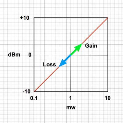
When
the two optical powers compared are equal, dB = 0, a
convenient value that is easily remembered. If the
measured power is higher than the reference power, dB
will be a positive number, but if it is lower than the
reference power, it will be negative. Thus measurements
of loss are expressed as negative numbers.
Here
is an Excel spreadsheet that calculates dB/power ratio
and dBm/milliwatts.
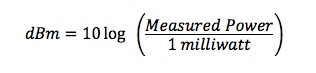
Measuring
Power
Measurements of optical power are expressed in units
of dBm. The “m” in dBm refers to the reference power
which is 1 milliwatt. Thus a source with a power level
of 0 dBm has a power of 1 milliwatt. Likewise, -10 dBm
is 0.1 milliwatt and +10 dBm is 10 milliwatts. Fiber
optic sources may vary from -20dBm to +20dBm and
receiver power may go as low as -40dBm.
dBm
= 10 log (measured power / 1mw)
When the power measured is 1mw, the equation
becomes:
dBm
= 10 log (1mw / 1mw) = 10 log (1) = 0 dBm
or
dBm
= measured power(dB) - reference power
(0dB) = dB
= measured power(dB) - 0
If the power
is greater than 1mw, say 2mw, the equation
becomes:
dBm
= 10 log (2mw/ 1mw) = 10 log (2) =
+3dBm (rounded off a little)
If
the power is less than
1mw, say 0.5mw, the
equation becomes:
dBm
= 10 log
(0.5mw/ 1mw) =
10 log (0.5) =
-3dBm (rounded
off a little)
That's
not hard to
remember.
Positive dBm
means power
greater than
1mw and
negative means
less than 1mw.
A good laser
source for a
singlemode
link will have
a power output
of ~ +3 to +6
dBm - 2-4mw -
coupled into
the fiber. A
VCSEL for
multimode
links should
have a power
around 0dBm -
1mw. And a
LED, used in
older
multimode
links, has a
typical power
of -10 dBm -
0.1mw or
100microwatts.
Example:
Here is an
example of the
conversion of
watts to dBm.
This meter is
reading
25microwatts -
that's
0.025milliwatts.
If we convert
to dBm, it
becomes
-16.0dBm. We
can easily
figure this
out using the
table of power
ratios above.
-10dBm is 1/10
of a milliwatt
or 0.100mW.
-6dB below
that is a
factor of 0.25
so 0.1mW X
0.25 = 0.025mW
or
25microwatts.
The other way
to figure it
is -10dB is
1/10 and -6dB
is 0.25 or
1/4th so
-16dBm is
1/40milliwatt
or
0.025milliwatts
or
25microwatts.
More
on dB math
below.
We
can show the relationship of dBm and milliwatts by the
graph at the top of the page or a version of the table
shown below it.
|
dBm
|
Milliwatts
|
dBm
|
Milliwatts
|
|
0
|
1.000
|
0
|
1.000
|
|
0.1
|
1.023
|
-0.1
|
0.977
|
|
0.2
|
1.047
|
-0.2
|
0.955
|
|
0.3
|
1.072
|
-0.3
|
0.933
|
|
0.4
|
1.096
|
-0.4
|
0.912
|
|
0.5
|
1.122
|
-0.5
|
0.891
|
|
0.6
|
1.148
|
-0.6
|
0.871
|
|
0.7
|
1.175
|
-0.7
|
0.851
|
|
0.8
|
1.202
|
-0.8
|
0.832
|
|
0.9
|
1.230
|
-0.9
|
0.813
|
|
1
|
1.259
|
-1
|
0.794
|
|
2
|
1.585
|
-2
|
0.631
|
|
3
|
1.995
|
-3
|
0.501
|
|
4
|
2.512
|
-4
|
0.398
|
|
5
|
3.162
|
-5
|
0.316
|
|
6
|
3.981
|
-6
|
0.251
|
|
7
|
5.012
|
-7
|
0.200
|
|
8
|
6.310
|
-8
|
0.158
|
|
9
|
7.943
|
-9
|
0.126
|
|
10
|
10
|
-10
|
0.1
|
|
20
|
100
|
-20
|
0.01
|
|
30
|
1,000
|
-30
|
0.001
|
|
40
|
10,000
|
-40
|
0.0001
|
|
50
|
100,000
|
-50
|
0.00001
|
|
60
|
1,000,000
|
-60
|
0.000001
|
Measuring Loss
If we have loss in a fiber optic system, the measured
power is less than the reference power, so the ratio of
measured power to reference power is less than 1 and the
log is negative, making dB a negative number. When we set
the reference value, the meter reads “0 dB” because the
reference value we set and the value the meter is
measuring is the same. Then when we measure loss, the
power measured is less, so the meter will read “ – 3.0 dB”
for example, if the tested power is half the reference
value. Although meters measure a negative number for loss,
convention has us saying the loss is a positive number, so
we say the loss is 3.0 dB when the meter reads – 3.0
dB.
Here is a short movie of what happens when we induce loss
in a cable by stressing it and watch the display of a
power meter. We start at -20.0dBm and after stress is
added to the cable to cause loss, the power level goes
down to -22.3dBm, showing our stress on the cable caused
2.3dB loss.
Here is the math of calculating this loss:
dB
= measured power(dB) - reference power (dB) = -22.3
dBm- (-20dBm) = -22.3 + 20 = -2.3 dB (remember
that subtracting a negative number has two minuses which
becomes a +.)
More
on dB math below.
Look at this animated simulation of a
laser/singlemode system with 1mw power from the source
and watch the meter reading.

Watch carefully as the transmitter couples a
signal into the fiber. As the signal pulse travels down
the fiber, it is attenuated by the fiber, suffers more
loss in the connection, then is attenuated more until it
reaches the receiver. See how the power in the signal
decreases as it travels down the fiber, becoming more
negative when measured in dBm.
Note 1: If you are used to making measurements of
loss with a light source and power meter, you are used
to loss being a negative number. But some
manufacturers of optical loss test sets, which include
a source and meter, show dB loss as a positive number.
They were probably confused by the fact that everybody
says "the loss is X dB" not "the loss is -X dB. And
they never looked at the math. Or learned math.
Note 2: Sometime in the past the IEC redefined
attenuation by flipping the power measured and the
power reference to make attenuation a positive number
(and therefore gain an negative number.) This is
averse to all other standards that use dB and
mathematical convention.
Undoubtedly some instrument manufacturer wanted the
definition that way and had no broad knowledge of
measurement convention. Nor did they understand
fiber optic power meters. We assume it was
just to make an optical loss test set read a positive
number, but it has certainly confused many people. See
below.
FOA
has a simulator to help you learn the process of
measuring loss with a light source and power meter.
Power-Measuring Instruments
Instruments that measure in dB can be either optical power
meters or optical loss test sets (OLTS). The optical power
meter usually reads in dBm for power measurements or dB
with respect to a user-set reference value for loss. While
most power meters have ranges of +3 to –50 dBm, most
sources are in the range of 0 to –10 dBm for lasers and
–10 to –20 dBm for LEDs. Only lasers used in CATV or
long-haul telephone systems with fiber amplifiers have
powers high enough to be really dangerous, up to +20 dBm –
that’s 100 milliwatts or a tenth of a watt!
The OLTS or the power meter on the dB scale measures
relative power or loss with respect to the reference level
set by the user. The range they measure will be determined
by the output power of the source in the unit and the
sensitivity of the detector. For multimode fiber, an OLTS
using a LED source will usually measure over a range of
0-30 dB, more than adequate for most multimode cable
plants which are under 10 dB loss. Singlemode networks use
lasers and may have loss ranges of up to 30-40 dB for
long-haul telecom systems, but campus cabling using
singlemode may only have 1-3 dB loss. Thus a singlemode
OLTS may be different for short and long systems.
Read
more on fiber optic instruments.
Conclusion
If you remember that dB is for measuring loss, dBm is for
measuring power and the more negative a number is, the
higher the loss, it’s hard to go wrong. Set your zero
before measuring loss and check it occasionally while
making measurements.
Here is an Excel spreadsheet
that calculates dB/power ratio and dBm/milliwatts.
More
on calibration
and metrology
(the science of measurements) in fiber optics.
More
pages of information on fiber optic measurements
Return to the FOA Guide
Table of Contents
Return to the FOA home
page
|
Understanding
dB Math
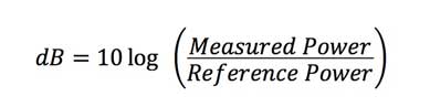
Let’s
start with the equation that defines dB that should be
familiar to most of you, the equation for attenuation in
fiber optics:
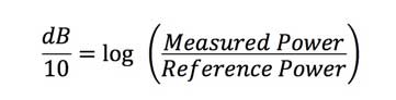
Let’s do some simplification. First manipulate the equation
to get the “10” over to the left side of the equation by
dividing both sides by 10:
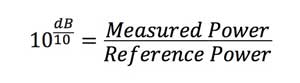
Now we need to deal with what is a “log” or logarithm
function. A logarithm is the exponent or “power” to which a
base must be raised to yield a given number, for example:

Based on that, we can further manipulate the equation above
to get the equation expressed as 10 to the power of dB/10:
So if
we convert 20dB this way, showing it step by step,
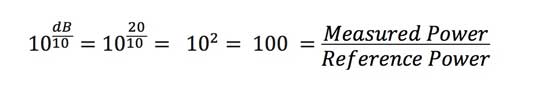
Thus 20 dB means the ratio of measured power to reference
power is 100:1. Likewise 10dB is a factor of 10 and 30dB is
a factor of 1000.
Now there is one more thing to learn about logarithms, they
can be positive or negative numbers. Consider this where dB
is negative:
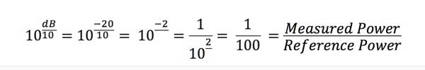
So if dB is negative, that means ratio of measured power to
reference power is less than 1 - the measured power is less
than the reference power or in fiber optic terms, we are
measuring a loss.
Note:
Sometime in the past the IEC redefined attenuation
thusly:
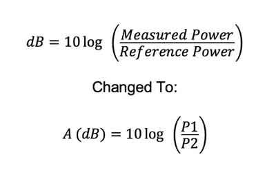
where
(quoting from the standard)
- A
is the attenuation, in dB
- P1
is the optical power traversing cross-section 1 (e.g.
before the attenuation you are measuring - what we
would call the "0dB" reference in testing cables)
- P2
is the optical power traversing cross-section 2. (e.g.
after the attenuation you are measuring - what we
would call the measurement of loss in testing cables)
Note 1
to entry: Attenuation is a measure of the decreasing optical
power in a fibre at a given wavelength. It depends on the
nature and length of the fibre and is also affected by
measurement conditions.
What Happened?
As we traced this definition in other IEC standards, we find
they are variations of this definition, and one specifically
states that it expresses attenuation as a positive
term.
So there you have it - why attenuation is positive - and
therefore gain - like a gainer on an OTDR - is a negative
number. The IEC standards just turned the measurement upside
down - reversing "Measured Power" and "Reference Power" to
get the term to become a positive number in dB when it's
attenuation.
IEC is unique. See References
below. Undoubtedly some instrument manufacturer wanted the
definition that way and had no broad knowledge of
measurement convention. Nor did they understand how fiber
optic power meters work.
Three issues with the IEC definition:
First:
There
are several reasons to object to this from a mathematical
and measurement standpoint. When you measure something
against a reference, it's common to divide the measured
value by the reference. Thus if something is getting
smaller, like attenuation, and the change is the measured
value decreases by 50% or half, you expect the ratio of
powers to be a number less than 1 because the value has
decreased, in this case the ration would be 1/2 or 0.5 0r
50%.
Consider what happens when using the equation above. If P1
is the reference and P2 the value after it decreases, the
ratio for the example above would be 2. Wouldn't anybody
assume that the measured value had increased instead of
decreased it the ratio was 2?
Second:
There are several reasons to object to this from a
mathematical and measurement standpoint. When you measure
something against a reference, it's common to divide the
measured value by the reference - like we do defining dBm
where the reference is 1mw.
We checked and the TIA and IEC standards for measuring
power, FOTP-95, still defines dBm this way. That's good,
because we're used to negative dBm being power smaller than
1mW and positive dBm being power larger than 1mW.
However if one makes an attenuation measurement using a
fiber optic power meter calibrated in dB and you used the
"Zero" control to set the reference,
the resulting measurement of loss will be a negative
number. Likewise if you measure the two powers in dBm,
the resulting measurement of loss will be a negative number,
if you understand negative numbers.
Note: dBm is defined as
Power(measured)/Power(1mw) (see FOTP-95, Sec. 6.2) and if
dBm were defined in this upside down manner, power
levels below 1mW would be positive numbers, not negative
as they are now, and power levels above 1mW would be
negative! How's that for confusing.
Third:
The definition assumes you are making measurements in linear
units - Watts, milliwatts or microwatts, then calculating
dB. Does anyone do that anymore? We don't think so.
Instruments measure in dB and dBm. Recognizing that, some
standards actually tell you how to calculate using simple
subtraction of dB or dBm measurements but reverse the values
so loss is positive and gain negative.
Maybe it's time to drop the definition from the standards or
at least provide descriptions of how one makes measurements
in dB.
References: The method for calculation of attenuation
in dB IEC uses in these fiber optic standards is definitely
not how measurements are normally defined. In fact we looked
at several dozen websites and the result was 100% -
attenuation is a negative value.
Rapid
tables
Wikipedia-
If P is
greater than P0 then LP is positive;
if P is less
than P0 then LP is negative.
Wikipedia
- definitions of the International Systems of Quantities -
If P is
greater than P0 then LP is positive;
if P is less
than P0 then LP is negative
TonTechnik-Rechner
- see Electric Power (telephone)
UC
San Diego Neurophysics - they get it! - (-3dB = half
power)
UC
Santa Cruz - with
the measured value less than the reference, we get a
negative dB value
Henry
Ott Consultants - The unit can be used to express
power gain (P2>P1), or power loss (P2<P1) -- in the
latter case the result will be a negative number.
Electronics
Notes - Where there is a loss, the deciBel equation will
return a negative value |
