Fusion Splicing
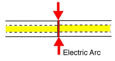
Fusion splicing is the process of fusing or welding two
fibers together usually by an electric arc. Fusion
splicing is the most widely used method of splicing as it
provides for the lowest loss and least reflectance, as
well as providing the strongest and most reliable joint
between two fibers.
Virtually all singlemode splices are fusion. Multimode
fibers can be harder to fusion splice as the larger core
with many layers of glass that produces the graded-index
profile are sometimes harder to match up, especially with
fibers of different types or manufacturers.
Fusion splicing may be done one fiber at a time or a
complete fiber ribbon from ribbon cable at one time. First
we'll look at single fiber splicing and then ribbon
splicing.
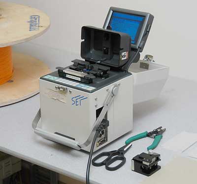
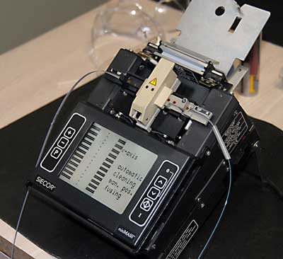
Fusion splicing machines are mostly automated tools that
require you preset the splicing parameters or choose
factory recommended settings that will control the
splicing process itself. All require the use of a
precision fiber cleaver that scribes and breaks (cleaves)
the fibers to be spliced precisely, as the quality of the
splice will depend on the quality of the cleave. Most
splicing machines come with a recommended cleaver.
Proper use of both the splicing machine and the cleaver
require carefully following the manufacturer's directions.
Each manufacturer's product is slightly different and
requires somewhat different procedures. Reading the
manuals and practice with the machine are important,
especially if the operator has not been trained on the
particular splicer in use.
Automatic Fiber Alignment
The ends of the fibers are on moveable stages which are
used to align the fibers and set the end gap
automatically. During the automated process, the splicer
will align the fibers using one of two methods:
Optical Core or Profile Alignment Systems (PAS)
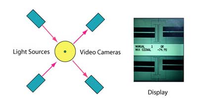
Optical Core Alignment (also called Profile
Alignment), an optical alignment technique, is used by
many models of fusion splicers. The two fibers are
illuminated from two directions, 90 degrees apart. From
the images in a video camera, software recognizes the core
of the fibers and aligns them automatically using movable
stages. The software also estimates splice loss after the
fusion splicing is complete. Ribbon splicers typically use
profile alignment.
Local Injection and Detection (LID System)
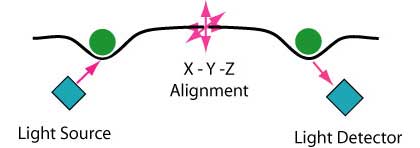
LID Core Alignment uses Local Injection and Detection of
light. Light is coupled into the fiber by bending the
fiber and shining a light source (LED or laser) on the
outside of one fiber, so some light is coupled into the
core. On the other fiber, the bend causes macrobending
losses that are measured by a photodetector, providing a
relative indication of light transmission through the
splice. The splicer measures light coupling through fiber
while moving fibers on actuators to get best transmission
which means the fibers are optimally aligned. The LID
system also checks transmission after splicing to estimate
splice loss.
Both techniques work well with most fibers. Refer to the
instruction manual or ask the manufacturer is there is any
question about using the splicer with the fiber you are
installing.
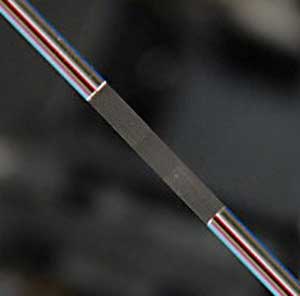
Splicing machines also generally have a heating device for
heat shrinking a protective sleeve over the finished
splice to protect it from moisture or other environmental
hazards. An alternate method using clamp-on protectors.
In addition to the splicer and cleaver, the tech doing the
splicing will need a set of cable preparation and fiber
stripping tools. Since much fusion splicing is done in the
outside plant, the splicing tech should have tools to
handle all types of loose tube cable, both gel-filled and
dry water-blocked, with various jacket styles, armor, etc.
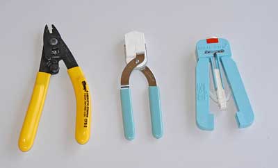
Fusion splicing requires stripping a longer length of bare
fiber than termination, so the choice of stripper is
important. There are three types of fiber strippers
available, known as (from Left) the Miller Stripper,
No-Nik and Micro-Strip. All three can work equally well,
and most techs choose the one they are most familiar with.
The Miller, perhaps the most rugged, has the disadvantage
of being "right-handed." The Micro-Strip allows setting
strip length for consistent strips. The No-Nik is careful
with the fiber but requires careful cleaning. Most
strippers are "sized" for the fiber coatings to be
removed, so ensure you have the proper stripper for the
fiber being stripped. Whichever stripper is used, care
must be taken to not nick the fiber during the stripping
process as it can cause cracks that may lead to fiber
failure sometime in the future. Strippers require careful
cleaning and immediate replacement if they become damaged
or worn.
The Fusion Splicing Process
(VHO
on cable preparation)
Detailed
Instructions For Fusion Splicing With EasySplicer
Prepare the cables to be spliced
Strip jacket, removing an adequate amount of jacket,
usually 2-3 m, for splicing and dressing the buffer tubes
and fibers in the splice closure. Leave the proper amount
of strength members to attach the cable to the closure.
Refer to the splice closure directions for lengths needed.
Clean all water-blocking materials using appropriate
cleaners.
Remove buffer tubes exposing fibers for splicing.
Generally splice closures will require ~1 m buffer tubes
inside the closure to and ~ 1 m fiber inside the splice
tray. Clean all water-blocking materials.
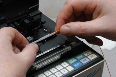
Prepare the fibers to be spliced
The process is the same for all splice types: strip, clean
& cleave.
Each fiber must be cleaned thoroughly before stripping for
splicing.
When ready to splice a fiber, strip off the buffer
coating(s) to expose the proper length of bare fiber
Clean the fiber with appropriate wipes
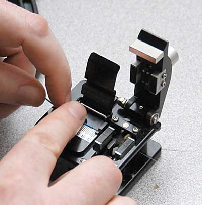
Cleave the fiber using the process appropriate to the
cleaver being used
Place the fiber into the guides in the fusion splicing
machine and clamp it in place
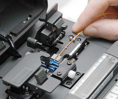
Repeat for the other fiber to be spliced
Running the splicer program
Choose the proper program for fusion splicing the fiber
types being spliced
The splicer will show the fibers being spliced on the
video screen.
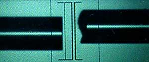
Fiber ends will be inspected for proper cleaves and bad
ones like the one on the right above will be rejected.
Automated Splicing
Fibers will be moved into position
Prefuse cycle will remove any dirt on the fiber ends and
preheat the fibers for splicing
The fibers will be aligned using core alignment method for
that splicer
The fibers will be fused by an automatic arc cycle that
heats them in an electric arc and feeds the fibers
together at a controlled rate
When fusion is completed, the splicing machine will
inspect the splice and estimate the optical loss of the
splice. It will tell the operator if a splice needs to be
remade.
The operator will remove the fibers from the guides and
attach a permanent splice protector by heat-shrinking or
clamping clam shell protectors.
Evaluating Splices
Modern splicing machines do all the splice processes
automatically, so the information below is for
information only. It is unlikely that an automatic
fusion splicing machine would show any of the problems
that were common with manual fusion splicers in the
past.
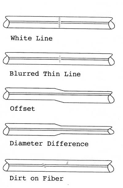
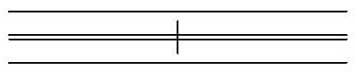
Good Splices
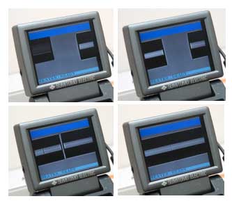
Visually inspect splice after the program has run,
using both X and Y views. Some flaws that do not
affect optical transmission are acceptable, as shown. Some
fibers (e.g. fluorine-doped or titanium coated) may cause
white or black lines in splice region that are not faults.
(Graphic from Sumitomo manual)
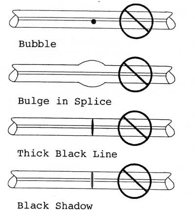
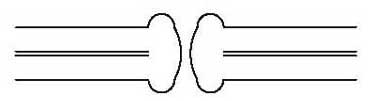
Bad Splices
Some flaws are unacceptable and require starting the
splicing process over. Some, like black spots or lines,
can be improved by repeating the ARC step, but never more
than twice. For large core offsets, bubbles or bulging
splices, always redo. (Graphic from Sumitomo manual)
Splice Problem Troubleshooting
Here are some common problems and likely causes.
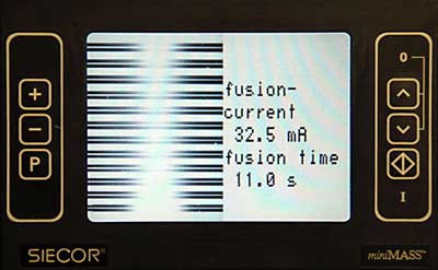
Not Fused Through
Fusion current too low
Prefusion time too short
Matchheads
Contaminated electrodes
Fusion current much too high
Prefusion time much too long
Prefusion current much too high
Autofeed too small
Gap too large
Constriction
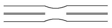
Current too high
Feed rate too slow
Prefusion time too long
Prefusion current too high
Gap too wide
Contaminated electrodes
Enlargement
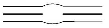
Autofeed too fast
Incorrect current
Bubble or Inclusion
Contaminated fiber end faces
Poor cleave
Fusion current too high
Prefusion current or time too low
Additional Problems
Fusion splicers generally have stored programs for most
fibers and the user can modify those program parameters or
create new ones. Refer to the instruction manual or ask
the manufacturer is there is any question about using the
splicer with the fiber you are installing.
It is sometimes necesary to splice older fibers, either in
restoration or modifying networks. Older fibers may become
brittle and hard to strip
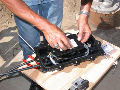
Splice Closures
After fibers are spliced, they will be placed in a splice
tray which is then placed in an splice closure. Outside
plant closures will be carefully sealed to prevent
moisture damage to the splices. The closure placed in
a designated protected place to complete the installation.
All cables that contain metallic elements like armor or
strength members must be grounded and bonded at each
splice point. Closures are designed to clamp cable
strength members to provide strength to prevent pulling
the cable out and seals to prevent moisture damage to the
splices.
Testing
Fusion splicers are used to create long cable lengths by
splicing multiple cable segments. Although the splicer
will give an estimate of the splice loss, the only way to
test it is with an OTDR.
Since OTDRs have directional errors, testing may be
required from both directions and averaged. Generally long
concatenated cables are tested with an OTDR and traces
kept for documentation in case of restoration.
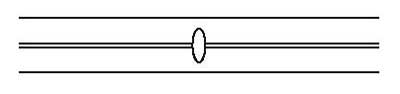
Ribbon Splicing (Mass Fusion Splicing)
Many high fiber count cables today are made from ribbons
of fibers, usually 12 fibers per ribbon. Splitting all
those fibers out to splice individually would be time
consuming, so ribbon fusion splicers, also called mass
fusion splicers, can splice entire ribbons at one time,
creating a splice that looks like this.
Ribbon splicers look similar to single fiber splicers and
work in much the same way, except the ribbons are treated
as one assembly, stripped, cleaved and spliced by special
tools while held in a special holder.
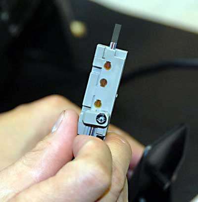
Below is the special holder used by the Corning ribbon
splicer shown.
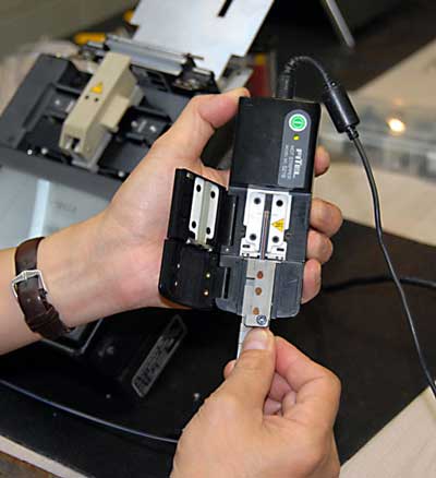
The holder is inserted in a special stripper that uses
heat to make stripping easier.
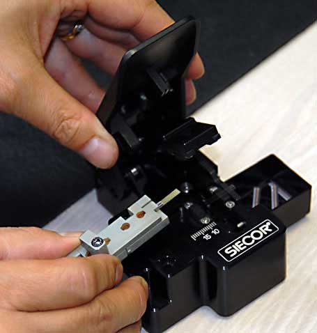
After stripping, the holder is placed in a special cleaver
that will cleave all 12 fibers at once.
The fixture with all the cleaved fibers is placed in the
splicing machine.
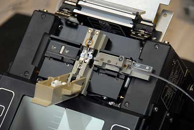
When the second ribbon is prepared, the unit is set for
automated splicing. The splices are shown being made
below.
Fusion Splicer Maintenance
All fusion splicers have maintenance requirements which
should be described in the operating manual. Besides
cleaning regularly, they require electrode alignment and
occasional replacement. Follow manufacturer's requirements
for servicing.
Virtual
Hands On, Fusion Splicing
Virtual
Hands On, Ribbon Splicing
Detailed
Instructions For Fusion Splicing With EasySplicer
Table of Contents: The FOA
Reference Guide To Fiber Optics
|
