
Testing FTTH PON network
Vladimir Grozdanovic
All optical fibers and cables must be tested and undergo a series of rigorous tests. There are manufacturer tests such as mechanical, geometrical, and optical tests. Additionally, manufacturers perform transmission tests, which are particularly important for contractors. All these tests are defined by ITU-T G.650 or EN 188 000 standards.
Transmission testing involves multiple measurements, such as bandwidth, optical power, attenuation, reflection, polarization, and chromatic dispersion. Testing of optical fibers and cables is required before installation, after installation, after fusion splicing, and of course, during maintenance and troubleshooting.
Pre-installation testing
After the cable arrives at the warehouse, prior to installation, its verification is required.This includes a visual inspection of the external appearance of packaging and the cable to determine required characteristics and detect any damages. Following visual inspection, if damage is visible on the cable on the reel, length and attenuation measurements of each individual fiber at 1310 nm and 1550 nm may need to be conducted (OTDR testing). If no damage is visible, testing a random sample of fibers should be sufficient. The deviation of measured attenuation values must not exceed 0.05 dB/km from the values specified by the cable manufacturer. All results are recorded and entered into the measurement protocol. If significant deviations and/or damages are observed, the cable should not be installed.
Post-installation and fiber connection testing
After cable laying and fiber splicing, measurements are necessary to ensure no damage occurred during installation and to verify the quality of fiber connections. Point-to-point measurements are required to determine total length, attenuation, and reflection, as well as the attenuation and reflection of characteristic events along the route. All connections require OTDR testing, connector presence, and visual inspection of their cleanliness using a microscope. Additionally, optical power is measured at transmission and reception using a stable test source and optical power meter. Throughout all testing, it is necessary to use the wavelengths of light that the system will use after being put into operation. All measurements should be recorded and documented, a crucial step that aids in maintenance and network issue resolution.
FTTH testing
FTTH networks are particularly
challenging to test due to optical splitters, multiple short links, wavelength
variations, and bidirectional communication. Optical splitters have significant
attenuation, can be of various types, and are often present in cascaded
arrangements. WDM mux/demux exhibit different performances depending on the
wavelength, and connectors can introduce significant reflections. Due to
generally shorter links and lower data transmission rates, in current solutions
such as GPON and XGS-PON, chromatic and polarization dispersion is negligible.
After the construction of an FTTH PON network, the first step is visual inspection and cleaning of connectors. After that, measuring optical power and conducting OTDR measurements at specific points are required. Measurements are performed in optical distribution boxes such as FCP (Fiber Concentration Point), BEP (Building Entry Point), ATB (Access Terminal Box), and others. All incoming optical fibers from the HE/CO without splitters are checked with an OTDR instrument. This is followed by checking attenuation and reflection, and if any deviations are present, the issue is addressed. After the splitters are installed, the network is usually active, and optical power measurements can be performed using the OLT transmitter as a test source. For this purpose, PON meters are used. If there are any discrepancies, first one should recheck all connections but if the optical splitter is the problem it should be replaced.
In case of individual or group issues, measuring optical power and conducting OTDR measurements from a specific point or user towards the HE/CO is required. More detailed testing and issue resolution on the FTTH PON network are described below.
Connector Inspection and Cleaning
Connector inspection and cleaning are the first and fundamental steps for any network. This is necessary during construction and throughout testing and issue resolution. Dirty connectors can introduce significant attenuation and disrupt services. Furthermore, dirty connectors can lead to damage, which is a major issue if it occurs on active equipment or instruments. Additionally, they can cause BIP errors (Bit-Interleaved Parity) and irregular operation of ONUs (rogue ONU).
Loss Testing
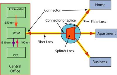
After construction completion, loss measurement is necessary. This is done using a test source, optical power meter, and reference cables or OLTS. For GPON systems, loss is measured at 1310 nm in the upstream direction and 1490 nm or 1550 nm (the more common wavelength for test sources) in the downstream direction. For other PON standards, measurements should be made at their operating wavelengths.
After activating the PON system, measurements are conducted without a test source, technicians only use PON meters for measuring optical power. Using a PON meter during issue resolution is one of the most common methods.
OTDR Testing
During the construction process of FTTH PON networks, OTDR measurements are performed on fibers without splitters. That procedure is well-known and generally straightforward. After the construction is completed, when problems arise, OTDR measurements are required on the network containing splitters.
OTDR testing is particularly challenging
for FTTH PON networks due to splitters and short links. FTTH PON has a P2MP (Point
to MultiPoint) topology in the downstream direction, while it is a P2P (Point
to Point) topology in the upstream direction.
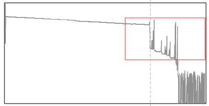
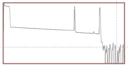
OTDR traces of a PON with a single splitter downstream (L) and upstream from one user fiber (R)
In the downstream direction, splitters lead to a significant drop in optical power, which is clearly observed on the OTDR. However, thereafter, there is branching into two or more paths, which poses challenges for analysis. The only information available for the fibers downstream of the splitter is the length of each branch fiber measured to the reflectance at the end of the fiber which only confirms the continuity of the fiber. If there is a problem on one of the branches, we cannot detect it in this way. Therefore, measurement in the opposite direction is required.
For all OTDR testing, OTDRs that allow measurements at 1310 nm and 1550 nm are most commonly used, which is entirely acceptable because the difference in attenuation at 1490 nm and 1550 nm is very small. Due to the very short links, the OTDR must have very high resolution. Short pulses are used to visualize all events. Additionally, OTDRs with a filtered wavelength of 1625 nm or more commonly 1650 nm can be used, enabling measurements on active fibers and identifying macrobends locations.
There are also specially designed instruments (e.g., EXFO OTDR FTB-1 with iOLM software solution or specialized instrument VIAVI Optimeter) that can display the network on the screen with attenuation, reflection, and optical power values at characteristic points (events). Based on attenuation and reflection, these instruments can identify splitters, connector joints, etc., significantly facilitating troubleshooting.
Other Testing
In addition to the described measurements, continuity testing of fibers and optical passive and active components is required before installation (splitters, WDM mux/demux, OLT, 1550 nm transmitters, and EDFA). To determine the attenuation of splitters, measurements must be done in both directions. WDM mux/demux also requires testing in both directions. Output power at the OLT, optical transmitter 1550 nm, and EDFA is measured using an optical power meter or a selective PON meter. The power depends on the chosen class and model of the device, as defined by the project. The power at the reception is particularly important. Excessive power leads to saturation, while insufficient power leads to reduced SNR. After the system is deployed, if it is necessary to adjust the optical power at the OLT, this can be done by replacing the SFP module class. On the other hand, the optical power at the transmitter and EDFA can be adjusted software-wise by lowering or increasing it on all outputs, or alternatively, fixed optical attenuators can be used where necessary.
Vladimir Grozdanovic is a graduate electrical engineer for telecommunications with more than 10 years of experience in access networks (HFC and FTTH) in large cable operators in Serbia (SBB and Jotel).
(C) 2024 The Fiber Optic Association Inc.