
| Visual
Tracing And Fault Location Two simple, inexpensive devices allow tracing and testing fibers for continuity or proper connections and one even is used to optimize splices or prepolished/splice connectors. Many of the problems in connection of fiber optic networks are related to making proper connections. Since the light used in systems is invisible infrared light (IR) beyond the range of the human eye, one cannot see the system transmitter light. By injecting the light from a visible source, such as a LED, laser or incandescent bulb, one can visually trace the fiber from transmitter to receiver to ensure correct orientation and check continuity besides. The simple instruments that inject visible light are called fiber tracers or visual fault locators. And in the end we will show you how to use an old cell phone's camera to detect light in a fiber optic system. Fiber Optic Tracer 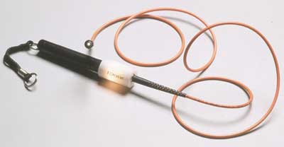
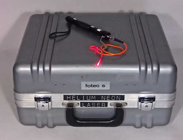 If a powerful enough visible light, such as a red laser or visible diode laser at 635-650 nm is injected into the fiber, tracing can be done on longer cables and high loss points can be made visible. The original VFLs were henium-neon (HeNe) lasers used in R&D labs. The field VFL was created in the mid-1980s by FOTEC, a fiber optic test equipment company. FOTEC packaged a visible red HeNe gas laser, power supply and battery into a suitcase to make it portable. Diode laser VFLs in small pen-shaped packages came more than a decade later. Most applications center around short cables such as used in telco central offices to connect to the fiber optic trunk cables. However, since it covers the range where OTDRs are not useful because of the dead zone of the OTDR, it is complementary to the OTDR in cable troubleshooting. This method will work on buffered fiber and even jacketed single fiber cable if the jacket is not opaque to the visible light. The yellow jacket of singlemode fiber and orange of multimode fiber will usually pass the visible light. Most other colors, especially black and gray, will not work with this technique, nor will most multifiber cables. However, many cable breaks, macrobending losses caused by kinks in the fiber , bad patchcords, spices etc. can be detected visually. Since the loss in the fiber is quite high at visible wavelengths, on the order of 9-15 dB/km, this instrument has a short range, typically 3-5 km.
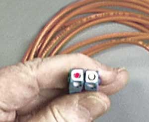 Finding Faults The higher power of a visual fault locator can find breaks in fibers or high losses around connectors in simplex cables. The light that escapes at a break, for example, will be visible through the jacket of the cable as shown below. This is extremely helpful in finding cable faults near the end of a cable where the dead zone of the OTDR makes it impossible to resolve faults. It also allows finding cracked fibers or bad splices in splice closures where an OTDR cannot resolve faults. 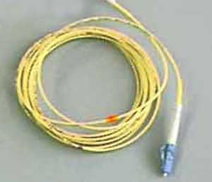 Sometimes there are problems in splice trays caused by fibers cracked when fibers are inserted in splice trays. The photo below shows an example of a fiber cracked in a splice tray illuminated with a VFL. This was the issue found in the first field trials of a VFL more than 30 years ago that led to its popularity in field troubleshooting. 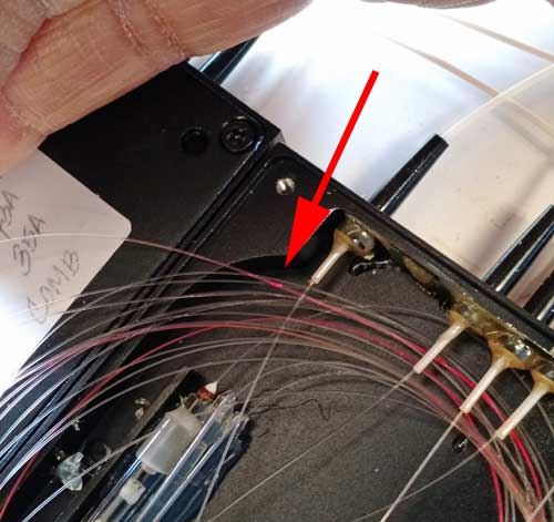 Photo courtesy Alan Kojima.
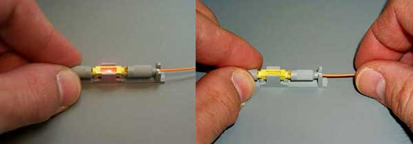 Optimizing mechanical splices (high loss at left, optimized at right. Using Cell Phone Cameras To See Infrared Light In Fiber Optics The camera in your cell phone is sensitive to infrared light - lots more than your eye - and can detect light in an optical fiber or from a transmitter. 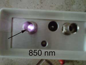
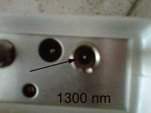 Camera phones sensors are very sensitive at 850 nm but less so at 1300 nm, like all semiconductor detectors. This phone could still see 1300 nm sources at around -20 dBm, making it very useful even for LED sources, and of course, perfect for lasers. This only works with earlier cell phone cameras - new ones are optimized for photography and do not have sensitivity in the infrared. We recommend you dig out that old cell phone from 2000-2005 and try it. If you don't have a fiber system or test source available, try the IR remote to your television to check the camera's sensitivity. We keep one of these old cell phones in our toolbox! Return to the FOA Guide Table of Contents |
|
|