|
Fiber
optic transmission systems (datalinks) mostly work
similar to that
shown below. They consist of a transmitter which takes
an
electrical
input and converts it to an optical output from a laser
diode
or LED. The light from the transmitter is coupled into
the fiber
with a connector and is transmitted through the fiber
optic cable
plant. The light is ultimately coupled to a receiver
where a detector
converts the light into an electrical signal which is
then conditioned
properly for use by the receiving equipment. Just as
with copper
wire or radio transmission, the performance of the fiber
optic
data link can be determined by how well the reconverted
electrical
signal out of the receiver matches the input to the
transmitter.
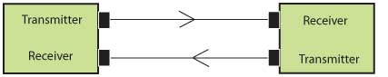
Since
it's
easier and cheaper to run full duplex over two fibers
transmitting
in opposite directions, links usually consist of two
transceivers
connected by two fibers as shown below. Some links, like
FTTH PON links
do use bidirectional transmission over one fiber because
they may have
three signals at different wavelengths to save having to
install
multiple fibers.
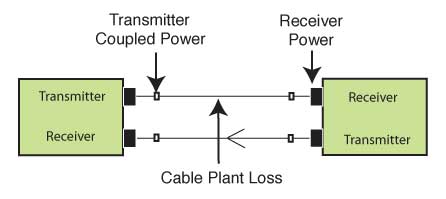
The ability of any fiber optic system to transmit data ultimately depends on the optical power at the receiver as shown below ,which shows the data link bit error rate (called "bit error rate" or BER) as a function of optical power at the receiver. Either too little or too much power will cause high bit error rates. Too much power, and the receiver amplifier saturates, too little and signal-to-noise (S/N) becomes a problem. This receiver power depends on two basic factors: how much power is launched into the fiber by the transmitter and how much is lost by attenuation in the optical fiber cable that connects the transmitter and receiver. The link loss budget is the difference between the transmitter output and the receiver input and is an important calculation made during the design phase of any system. When testing, since typically both transmitters and receivers have receptacles for fiber optic connectors, measuring the power of a transmitter is done by attaching a test cable to the source and measuring the power at the other end. For receivers, one disconnects the cable attached to the receiver receptacle and measures the output with the meter. That measured value must be within the specified loss budget of the link. Datalinks can be either analog or digital in nature. Both have some common critical parameters and some major differences. For both, the optical loss margin is most important. This is determined by connecting the link up with an adjustable attenuator in the cable plant and varying the loss until one can generate the curve shown below. Analog datalinks will be tested for signal to noise ratio to determine link margin, while digital links use bit error rate as a measure of performance. Both links require testing over the full bandwidth specified for operation, but most data links are now specified for a specific network application, like AM CATV or RGB color monitors for analog links and SONET, Ethernet or Fibre Channel for digital links. 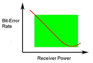
The optical power margin of the link is determined by two factors, the sensitivity of the receiver, which is determined in the bit error rate curve above and the output power of the transmitter into the fiber. The minimum power level that produces an acceptable bit error rate determines the sensitivity the receiver. The power from the transmitter coupled into the optical fiber determines the transmitted power. The difference between these two power levels determines the loss margin of the link. If the link is designed to operate at differing bit rates, it is necessary to generate the performance curve for each bit-rate. Since the total power in the signal is a function of pulse width and pulse width will vary with bit-rate (higher bit-rates means shorter pulses), the receiver sensitivity will degrade at higher bit-rates. Every
manufacturer of datalinks components and systems
specifies
them for receiver sensitivity (perhaps a minimum power
required)
and minimum power coupled into the fiber from the
source. Typical
values for these parameters are shown in the table
below. In order to
test them properly, it is necessary to know the test
conditions.
For data link components, it includes input frequency or
bitrate
and duty cycle, power supply voltages and the type of
fiber coupled
to the source. For systems, it will be the diagnostic
program
needed by the system. Multimode systems operating at
gigabit rates and
above will have derating factors for the bandwidth of
the optical fiber
being used.
Within
the datacommunications links and networks, there are
many vendor proprietary fiber optic systems, but there
are also a
number of industry standard networks. These networks
have agreed
upon specifications common to all manufacturers'
products to insure
interoperability. The
FOA Guide has a page that shows a summary of many
these systems.
Testing
and Troubleshooting Networks Testing
a
fiber optic network is straightforward using a fiber
optic power
meter and some good patchcords. However, fiber optic
networks should
only be tested when initially setting up the system or
troubleshooting
network transmission problems. Otherwise, lock up the
connections and
leave them alone! Fiber optic networks are much more
reliable than
other transmission methods and do not need periodic
maintenance. Warning: Handling and Cleaning Procedures Fiber optic connectors and cables should be handled with care. While they are not delicate, they can be damaged by improper handling. Do not bend cables too tightly, especially near the connectors, as sharp bends can break the fibers. Do not drop the connectors, especially if they do not have a dust cap on the ferrule, as they can be damaged by a blow to the optical face. Do not pull hard on the cable attached to the connector, as this may break the fiber in the backshell of the connector or cause pistoning if the bond between the fiber and the connector ferrule is broken. If
there is any question about the condition of the
connectors,
clean
them before testing. A fiber optic inspection
microscope
with appropriate stages to hold the connectors should
be used
to verify the condition of the connectors if there is
any doubt
about their cleanliness or physical condition. Fiber optic networks are always specified to operate over a range of loss, typically called the system margin. Either too much loss or too little loss can be a problem. If the loss is too high, the signal will be low at the receiver, causing a poor signal to noise condition in the receiver. If the loss is too low, the power level at the receiver will be too high, causing receiver saturation. Both these conditions will cause high bit error rates in digital systems or poor analog signal-to-noise (S/N) performance.
If the receiver power is low, the transmitter power should be measured by disconnecting the source jumper cable at the first available connector and measuring the power with the fiber at that point. Alternatively, one can disconnect the cable at the transmitter and use a known good test jumper to measure the coupled power. If the output is measured through a short network jumper cable ( less than 10 meters ), no compensation for jumper loss is necessary. For longer jumpers, some compensation may be necessary. If receiver power is low, but transmitter power is high, there is something wrong with the cables. They must be tested at every connection to isolate the bad cable(s) and or connectors (see below.) This can be done from either end with a power meter and source or, if the cable plant is sufficiently long, an OTDR. Starting from the transmitter or receiver end, follow the network cables to every patch panel. Disconnect the connector and measure the power at each point. By making measurements in dB, one can easily calculate the loss of the cable network to each point by subtracting successive readings. When
a suspect cable is found, by noting a larger than
expected
loss in the cable link, the suspect cable needs testing
by the
appropriate method described above. If a cable has
attenuation
that is higher than specifications, but still transmits
light,
check connectors on a microscope to determine if they
have been
damaged and should be replaced. If the connectors look
good, the
best solution may be to replace the cable or switch to a
spare.
If a visual fault locator is available, it can be used
to visually
locate breaks in the fiber and find broken connectors.
Under some
circumstances, such as high loss in long jumper or trunk
cables,
an OTDR (optical time domain reflectometer) can be used
to diagnose
cable faults.
Testing The Installed Cable Plant Test the complete cable plant, including all individual jumper or trunk cables, for loss, using a power meter and source and the double-ended method described above in the chapter on testing the cable plant. Use the OFSTP-14 (double-ended) method, since system margin specifications include the loss of connectors on both ends of the fiber. If the end-to-end (transmitter to receiver) loss measurement for a given fiber is within the network margin specification, the data should be recorded for future reference. If the loss is too low, notation should be made that that fiber will probably need an inline attenuator to reduce receiver power to acceptable levels. If the loss is too high, it will be necessary to retest each link of the complete cable run to find the bad link. Possible causes of high end-to-end link loss are bad connectors, bad splice bushings in patch panels, cables bent too tightly around corners, broken fibers in cables or even bad launch or receive cables or instruments. There are only two ways to find the problem: test each segment of the cable individually to find the problem or and OTDR ,if the lengths are long enough for viewing with the limited resolution of the OTDR. Do
not use an OTDR for measuring end to end loss; use it
for troubleshooting problems. It will not
accurately measure actual link loss as seen by the
actual transmitters
and receivers of the fiber optic link. As normally used,
the OTDR
will not count the end connectors' loss. The OTDR uses a
laser
which has very restricted mode power distribution, which
minimizes
the loss of the fiber and the intermediate connectors.
Finally,
the difference in backscattering coefficients of various
fibers
leads to imprecise connector loss measurements. See
OTDRs.
Transceiver Loopback Testing The datacom capabilities of the network can be tested with a loopback test . This test uses a calibrated fiber optic attenuator which has either a fixed or variable dB loss placed between the transmitter and receiver on a piece of equipment to see if it can transmit data to itself. Many types of network equipment have diagnostics to do loopback testing. This will test the transmitter and receiver of the unit under standard data transmission conditions over the specified link loss budget. 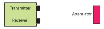
Some
equipment can also institute an electrical network
loopback
test, where the loopback path is all electronic inside
the equipment, looping
back over the entire datalink to the equipment on the
far end
of the link. If both ends of the link pass a unit
loopback test
but fail a network loopback test, the problem is in the
cables,
which then need testing by the methods described above. More on fiber optic data links. |
|
|