- Frequently
Asked Questions On OTDRS And Hints On Their Use
OTDRs, also known by their technical name optical time
domain reflectometers, are valuable fiber optic testers
when used properly, but improper use can be misleading
and, in our experience, lead to expensive mistakes for
the contractor. We have been personally involved in
several instances where misapplication of OTDR testing
has cost the contractor as much as $100,000 in wasted
time and materials. Needless to say, it's extremely
important to understand how to use these instruments
correctly.
What Is The Difference Between OTDR Testing And
Insertion Loss Testing?
An insertion loss test made with a light source and
power meter is a simple test that is similar in
principle to how a fiber optic link works. A light is
placed on one end of the cable and a power meter
measures loss at the other end, just like a link
transmitter and receiver use the fiber for
communications.
An OTDR, however, works like RADAR. It sends a pulse
down the fiber and looks for a return signal from fiber
backscatter and reflections from joints, creating a
display called a "trace" or "signature" from the
measurement of the fiber. From this trace, the OTDR
calculates fiber length, attenuation and joint loss. So
it does not “measure” loss directly, it implies it from
the trace.
When is OTDR Testing Appropriate?
The answer to this question has several aspects.
Let’s start with “What are we trying to test?”
OSP: In a long outside plant cable with many splices,
the OTDR is used to ensure that the cable has not been
damaged during installation and each splice is properly
made. Results are archived with other documentation to
be available if restoration is necessary in the future.
Later OTDR testing may be used for troubleshooting
problems like finding locations of cable breaks caused
by dig-ups. Generally, OSP networks are also tested with
a LSPM (light source and power meter) also called an
OLTS (optical loss test set.)
Premises: Premises cabling, however, has short cable
runs and almost never includes splices, so the
requirement of OTDR testing appears to be as an
alternative to insertion loss testing with a light
source and power meter, which in reality, is
inappropriate.
We recommend that insertion loss testing be done even
when OTDR testing is required by installation contracts.
In our experience, OTDR testing of premises cabling
systems is often required by users who do not really
understand when OTDR testing is appropriate or even what
an OTDR is. A knowledgeable contractor should be able to
educate the user on proper testing requirements.
New international testing standards, however, accept
both OTDR testing and insertion loss testing, even for
short premises multimode cable plants. The differences
in the measurement techniques used by OTDRs and a light
source and power meter means that OTDR testing,
especially on longer premises cable plants with higher
loss, may not be comparable to measured insertion loss
or the actual loss the communications system will
experience.
The international standard that allowed OTDR as well as
LSPM (light source and power meter) testing based that
decision on tests performed on cable plants appropriate
for 10G Ethernet which had losses of <2dB. In the
real world, multimode cable plants in premises
installations can have losses of 5-10 dB or more. OTDR
tests will generally not correlate with LSPM tests (or
often with other OTDRs!) which test the cable plant more
like how the cable plant is used by communications
equipment, and usually OTDR results are lower, setting
up the network owner for a problem when the
communications electronics are installed.
For this reason alone, we recommend that insertion loss
testing be done even when OTDR testing is required by
installation contracts.
Most of the technical calls we get at FOA regarding
problems using OTDRs on premises cabling systems are
caused by users who don't know what an OTDR is requiring
them for testing their installation just because
somebody told them to or they assume a bigger, more
expensive instrument gives better data.
Next: What Can The OTDR “Test”?
OTDRs use an indirect measurement process, have poor
length resolution and unique measurement errors that
limit its accuracy in testing cable plants. It is not
considered a replacement for insertion loss testing by
knowledgeable fiber optic personnel.
From a more technical standpoint, the first and most
important consideration for OTDR use is the length of
the fibers to be tested. Most OTDRs are designed for
long cable plants, especially singlemode OTDRs, and may
be inappropriate for short cables. Some multimode OTDRs
are now usable for short length multimode premises
cables but only if they are properly set up before use
and launch and receive cables have connections with low
reflectance. Furthermore, on short cables or even
relatively long ones with highly reflective events,
“ghosts” caused by the high reflectance
OTDR measurement of joint lost are directional,
dependent on the backscatter coefficient of the fiber,
causing measurement to vary by 0.25 dB or more depending
on direction.
If you are looking to test a cable plant to see if it
will support a communications system’s loss budget, you
do not want OTDR testing. If your network is short, the
OTDR will not give you valid data.
The second most common tech question we get at the FOA
is from people trying to use an OTDR when it’s
inappropriate.
Do I Need Training To Use An OTDR?
"My OTDR manufacturer tells me its fully automatic and I
just push a button and it gives me a PASS/FAIL result
like my “Cat 5” tester. They say I don’t need any
training."
Let’s just say that the majority of calls we get at the
FOA involve OTDRs being used by people who are ignorant
of their use, either trying to use them for cable plants
that are too short or full of ghosts, their launch
cables are too short, the setup wrong, or they simply
don’t know how to interpret the OTDR trace. We have many
examples including one instance where over $100,000
worth of cable was rejected and pulled out when it was
perfectly OK but the OTDR user did not understand the
trace. We have had calls from people trying to test 70m
singlemode cables without a launch cable, MM cables with
SM OTDRs and vice versa, and many more.
If you are using an OTDR without training, you are going
to have big problems.
- Why
Do I Need A Launch Cable On The OTDR?
- OTDRs are
always used with a launch cable and may use a receive
cable. The launch cable, sometimes also called a "pulse
suppressor," has two major reasons for its use:
- 1. The launch
cable allows the OTDR trace to settle down after the
test pulse is sent into the fiber so you can analyze the
beginning of the cable you are testing. The large event
you see right in front of the instrument on the OTDR
trace is caused by crosstalk within the instrument and
reflectance from the connector on the face of the OTDR.
The long recovery time from this overload pulse means
the OTDR cannot make any useful measurements near the
instrument itself. The launch cable has also been called
a "pulse suppressor" because it allows time for the OTDR
to settle down from this initial overload. If possible,
singlemode OTDRs should have APC connectors on the front
panel to reduce reflectance. Also a short connection
cable attached to the OTDR before the launch cable that
never gets removed from the OTDR prevents excess wear on
the panel connector.
- 2, The launch
cable provides a reference connector for the first
connector on the cable under test to determine its loss.
A receive cable may be used on the far end to allow
measurements of the connector on the end of the cable
under test also.
What Is The Resolution In Length Of The OTDR?
Most OTDRs have a display range digitized to about
10-20,000 parts, so on a 20km range, the display
resolution is 1m, or on a 2km range it would be 0.1m.
The actual resolution of the OTDR is usually thought of
as its ability to distinguish between two points on the
cable, like intermediate patchcords or closely spaced
splices. The actual resolution is determined by the
width of the test pulse and the bandwidth of the OTDR
receiver and is usually much longer than the display
resolution. A 100ns pulse, for example, equals about
20m, but the depending on the shape of the test
pulse, the OTDR may not be able to distinguish events
2-3 times that length.
- See the demonstration
below for a way to prove this to yourself.
I Have Heard The OTDR Measures Fiber Length, Not
Cable Length. How Do I Correct For That?
First, what are the sources of error? The OTDR uses the
speed of light in the fiber (from the index of
refraction) to calculate the length of the fiber. Also,
most cables have 1-2% excess fiber (less on ribbon
cables) to prevent fiber stress under cable tension.
Some manufacturers of cable can provide that information
for your testing. If you do not know the index of
refraction/velocity of propagation or the ratio of
excess fiber, you can estimate it or, if you have a long
spool of cable, calibrate it.
Just measure the fiber on the spool of cable with the
OTDR, then look at the cable jacket for length markings
to get the actual length of the cable from the printed
markings at each end of the cable. Use the OTDR’s
calibration feature to set the index of refraction to
the value that makes the OTDR read the same as the
marked length of the cable.
Directional
Results Can Be Confusing: I am testing a cable with
OTDR. I have a limit 0.2 db loss per splice. I use bi
directional analysis. In some fibers from A>B
direction i have 0.25 loss but in B>A it doesnt show
up that splice at all. I changed the pulse width but
nothing happened. Any ideas?
You are
seeing the directional differences. For a splice with 0.25
dB loss in one direction and 0 dB in the other, the
average is (0.25+0)/2 = 0.13 dB loss. If you shoot in both
directions and overlay, the software should recognize that
there should be events in both directions, input a "0 dB"
event and average accordingly. Most OTDRs also allow
setting a threshold for detection of events and that must
be set correctly to recognize events. There are many times
a splice is undetectable in an OTDR trace due to good
splices and the simple fact that the OTDR measurement
technique itself is limited.
How can
we differentiate a ghost from a real event?
A ghost
will not have any loss, it will be at equal distance from
a highly reflective event (look for repetition), tends to
be in the middle of noise after the end of the cable.
What
are good values to set a OTDR to for PASS/FAIL?
Splice threshold
Reflectance threshold
Slope threshold (slope is attenuation coefficient)
End threshold (depends on whether you 1) use receive
reference cable which would be a normal connection loss or
2)the length of the cable and the noise floor of the
measurement. Best to make sure the trace is not noisy to the
end and have 2-3dB from the cable backscatter level to the
noise floor.
Application
|
Splice
|
Connector
|
Reflectance
|
Attenuation
|
Singlemode
long distance (>5-10km)
|
<0.1dB
(fusion)
|
<0.3dB
|
>-40dB
(that means -41dB or more)
|
0.4dB/km
at 1310nm, 0.25dB/km at 1550nm
|
SM
short links
|
<0.1dB
(fusion)
|
<0.3dB
|
>-50dB
(that means -51dB or more)
|
0.4dB/km
at 1310nm, 0.25dB/km at 1550nm
|
MM
|
0.3dB
(fusion or mechanical)
|
<0.5dB
|
>-30-35dB
|
3.0
dB/km at 850nm, 1dB/km at 1310nm
|
- Uncertainty
of OTDR Test Results
- We received a
call from a contractor who had tested a cable plant for
an end user using an OTDR. The user had several others
do the same test and got different results, not widely
different, but different enough to make him wonder why.
The same thing happens with OLTS testing too, but for
slightly different reasons. This conversation inspired a
short tutorial which follows:
- Two Types of
Measurement Errors
-
Measuring a physical parameter always involves errors.
Unfortunately you never know the real value to begin
with, so all you can do is to estimate the error based
on the possible sources of error in making the
measurement. There are two types of errors, random and
systematic.
-
Random errors are what you see when you make a
measurement multiple times and get a slightly different
value each time. Hook up your instrument and make the
measurement, disconnect and try again. Each time, the
result will be slightly different. Generally one should
make several measurements, average them and use the data
to calculate the random error, called standard
deviation, to understand the uncertainty of the
measurement.
-
Systematic errors are how the average measurement
differs from the real value, which can be caused by some
problem in setup or calibration. Unfortunately, it’s
hard to determine the systematic error, but some
possible ways exist sometimes.
- Let’s look
at OTDR measurement uncertainty from both a random
and systematic viewpoint.
- Random Errors
-
Testing loss with an OTDR requires a launch cable that
connects to the fiber in the cable under test, taking a
trace and analyzing the trace, either manually or using
some preprogrammed auto-test function. This leads to
several random errors in loss measurement which may
include:
- 1.
Variation in loss of the connection of the launch cable
to the cable under test caused by alignment variations
each time it’s connected, dirt, temperature, etc.
- 2.
Changes in stress of the launch cable or cable under
test which can be caused by temperature variations or
physical movement of the cable.
- 3.
Changes in the mode power distribution of launched
pulses which can affect both multimode and
singlemode cables (short SM may not be single-mode-it
may take hundreds of meters!)
- 4.
Noise in the OTDR trace, with the effect greater effect
with less averaging.
- 5.
How the user sets the markers on the trace for each
measurement. This is affected by pulse width (risetime)
and the reflectance from an event which can overload the
OTDR and cause difficulties in determining where the
fiber baseline is located.
- Systematic
Errors
-
When you set up the OTDR, you have to make certain
set-up decisions, including range, wavelength, fiber
glass index of refraction, pulse width, number of
averages, etc. that affect the measurement uncertainty
for every measurement.
- Length
Measurement
- 1.
The range may affect the time base of the OTDR which is
used (along with index of refraction) to calculate the
length of the fiber.
- 2.
The index of refraction (n) is a direct expression of
the speed of light in the fiber (V=C/n). Distance is
calculated as “time X speed.” Most OTDR users use a
generic value, but sometimes the actual value for the
fiber being tested is known.
- 3.
Each cable has excess fiber, typically ~1%, to prevent
stressing the fiber when pulled. The OTDR measures the
length of the fiber, not the cable. It can be calibrated
for the cable under test if one knows the length of the
cable and uses that to calculate a cable-specific index
of refraction.
- 4.
The pulse width may cause systematic errors in the
measurement of length, since wider pulses have longer
risetimes which make placing the markers consistently
more difficult.
- Loss
- 1.
Setting markers for measuring loss is affected by the
width of the test pulse. Longer pulses have longer
risetimes which make setting markers consistently more
difficult. Wider pulses cause greater reflectance from
connectors and affect both the shape of the reflected
pulse and the shape of the return to the fiber baseline,
causing uncertainty on how the markers are set. Noisy
traces are wider, which can lead to systematic errors.
- 2.
Manually setting markers generally will introduce random
errors, as the operator sets their location each time,
but can introduce systematic errors due to the way the
operator typically works.
- 3.
Auto-test programming may introduce systematic errors
depending on the pulse width, reflectance, range,
averaging, etc. Generally auto-test should not be used
until it has been compared to manual analysis.
- 4.
Connectors on different launch or receive cables will
change the measurements systematically.
- 5.
The length of the launch cable may affect SM or
multimode measurements. A SM launch cable should be
500-1000 m long to ensure the test signals are
singlemode. Multimode fiber will change mode power
distribution with length.
- 6.
Any mode conditioning on a MM cable (e.g. mandrel wraps)
will affect the modal conditioning on the downstream
part of the test where the test pulse from the OTDR goes
out from the OTDR. On the return backscattered light,
the fiber modes will be fully filled.
- 7.
Instrument calibration will cause systematic errors. Few
users ever calibrate OTDRs, but the time base and
linearity of the amplifiers can affect the measurements.
- Uncertainty of
Results
- So what can
you expect? Length may vary by several percent on
different OTDRs. Loss can vary by several tenths of a dB
on short lengths and proportionally more on long cable
plants for different OTDRs.
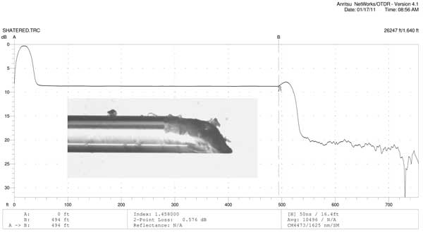
Fiber
Loss Errors On Short Cables
A
contractor had a customer who required OTDR testing of
installed cables, including measuring the attenuation
coefficient of the fibers in the cables. Fiber attenuation
readings well above the expected values and those required
by the contract with the user. Under some questioning, we
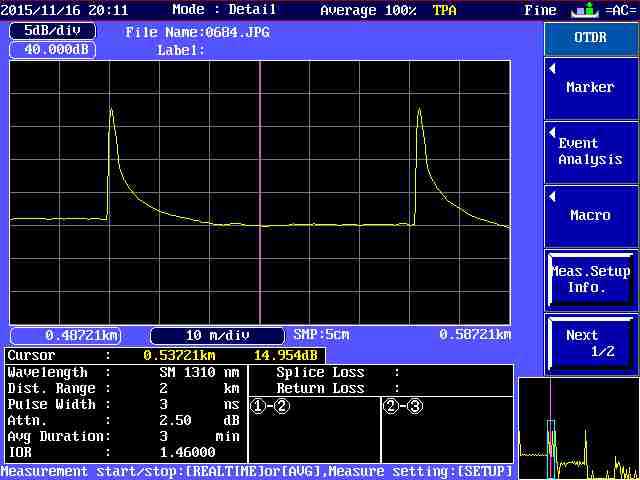
found out the cables were very short, so the traces looked
like this:
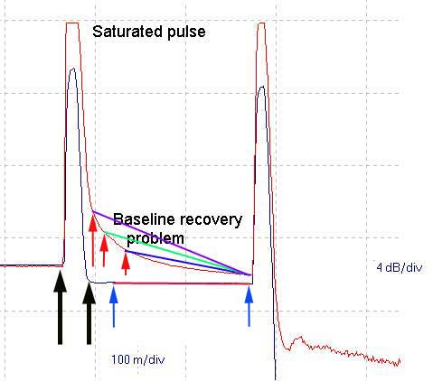
The problem was the recovery from the reflectance overload
at the connection between the launch cable and the cable
under test was not recovering quickly, so there was not
enough usable fiber trace to get a valid reading of the
slope of the fiber which is the attenuation coefficient.
When the marker is placed on the tail of the recovery pulse
(the red arrows), the
slope of the measured trace is much higher than the actual
slope of just the fiber attenuation, leading to values that
cause the fiber to fail testing even if it is good. To get a
valid reading the pulse must fully recover to the baseline
of the fiber as shown by the black arrows and then the
markers can be placed as shown in the
blue arrows to make a fiber attenuation coefficient
measurement.
But to make this measurement, the fiber must be long enough
and the OTDR resolution high enough.
Testing
Bare Fibers With OTDR
Q: We are starting to test some OPGW cables. We
have an OTDR but we don’t find some reusable connectors.
If we have to test an OPGW with 48 fibres, we can’t set up
48 SC connectors!
Are there some reusable connectors in the commerce?
A: I assume you
mean you need to test with a bare fiber on the OPGW. For
testing bare fiber, use a splice, not a connector. Have a
long pigtail on the OTDR as a launch cable, long enough
for the test pulse to settle, say 100-500m, then use a
splice for a temporary connection. You can fusion splice
the fibers then cut the splice out or use a removable
splice like the Corning Camsplice
(http://catalog.corning.com/opcomm/en-US/catalog/ProductDetails.aspx?cid=&pid=17929&vid=18219)
If you use a mechanical splice, you need a high quality
cleaver just like with fusion splicing and after several
uses, you need to add more index matching gel or liquid -
mineral oil works OK. See
the FOA page on Testing
Bare Fiber.
- OTDR
Calibration
Q: I read on your website information about
ODTR, and I'm curious if you could offer some more
information. I am interested in all compatible standards
considering OTDR Calibration. So far I managed to find
out that there is IEC 61746-1 standard for Calibration,
and also TIA/EIA-455-226 which is adoption of IEC
61746-1. And I concluded that those 2 are surely
internationally approved and do the same thing. I found
in some website the offer for calibration performing
both NIST traceable, and TIA 455.
I could not find out what is relation between TIA and
NIST traceable calibration standards ( if there are
any), is it the same or those 2 are compatible (if
u use one of those for OTDR calibration it is
enough)or those 2 are different and you need to perform
both.
A: OTDR
calibration is not a simple task like calibrating power
meters.
Calibration of OTDRs involves the time base for the OTDR
that uses the index of refraction of the fiber or
nominal velocity of propagation (NVP) of light in the
fiber to calculate distance and the linearity of the
power measurement of the receiver. NVP is, of course,
dependent on wavelength.
The debate over OTDR calibration has always been whether
a standard fiber method of calibration that involved
calibrating every OTDR to read the trace identically or
an electronic method of calibrating the OTDR timebase
and receiver was a better method.
NIST was approached for OTDR calibration in the 1980s
and considered making a transfer standard for use in
calibrating OTDRs. It was originally intended to be a
sample fiber of known index of refraction and length
with splices and connectors of known loss. However the
project was never completed as it would require many
different "standard fibers" and could not be made
agreeable to all parties.
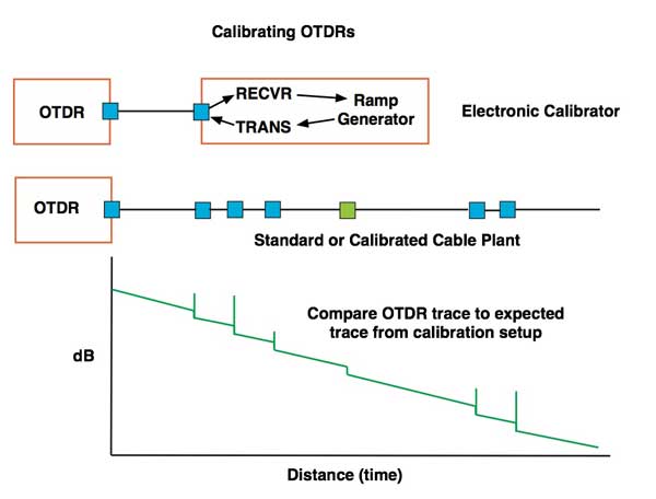
Others thought an electronic/optical calibration based
on a device that would simulate the trace from a cable
was more accurate. That involved an instrument that
would be triggered by the OTDR test pulse and would then
generate an optical power declining over time to
simulate the OTDR trace. Both these methods have been
used since, but NIST never produced an OTDR calibration
system like they did for optical power meters (I worked
on that one myself.)
There is IEC 61746-1 standard for Calibration, and also
TIA/EIA-455-226 which is adoption of the IEC document.
Other than the IEC document, I know of no other
standards or traceable calibration by a national
standards lab.
Since there is no standard fiber, perhaps the best
method of "calibrating" the instrument is sending it
back to the manufacturer who can test the timebase and
receiver linearity and confirm their performance. And,
of course, they can do all the other updates for the
given model of OTDR.
Then it is left to the user to choose the proper NVP or
index of refraction for the fiber or calibrate it for
the cable length (including average excess fiber in the
cable.) And deal with the differences in backscatter
that cause directional errors in loss of splices and
connections.
Or maybe, one realizes that OTDRs are better considered
"qualitative" instruments instead of "quantitative"
instruments and just accept the fact that the data has
quite a bit of uncertainty.
I’m Troubleshooting A Break In A Long Cable Run But I
Don’t Know The Correction Factor For Fiber Vs Cable
Length. What Can I Do?
Here is a perfect example of why you need cable plant
documentation. If you have the data from the original
design and testing, you should have the actual length of
the cable plant. With that you can calculate the point
of the break very closely. Here is an example:
Let’s say we have a 10km cable with a break around 6km
from one end. From one end, the OTDR says the distance
to the break is 6500m and from the other end it says
it’s 4000m.
Total length of OTDR cable length: 6500+4000=10,500m
If the actual cable length is 10,000 m, the correction
factor is:
Actual length/measured length = 10000/10500 = 0.952 =
correction factor
Thus our 6500m measurement is actually 6500X0.952 =
6190m and from the other end it’s 3810m.
If you do not have documentation, try to calibrate the
OTDR using a section where you can get real length data
from the cable jacket.
Sometimes My Traces Show Big Reflections From The End
Of The Cable But Sometimes It Shows None At All. Why?
The reflection on the end of the cable depends on the
end of the fiber. If it’s broken and ragged, you will
see practically no reflection, but a perfectly cleaved
fiber will show a giant reflection peak.
Look at these three traces:
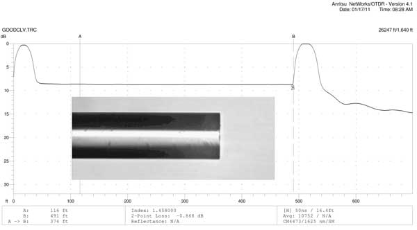
Note how the cleaved fiber has a high reflectance,
reaching saturation on the OTDR trace
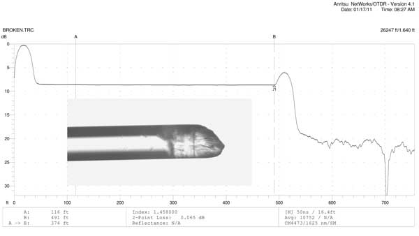
The broken trace shows a small reflectance.
The shattered fiber shows virtually no reflectance.
- Interpreting
OTDR End Reflectance Peaks (from Terry O'Malley)
Close
inspection of Fresnel Reflections (Reflectance
Peaks) May Yield Useful Information
by Terry O'Malley
When inspecting and analyzing Fresnels, particularly
at the end of a system, testing technician should pay
close attention to the trace of the recovery slope of
all Fresnels, especially the end of system Fresnel.
Sometimes it is possible to detect an upward, smaller
spike in the recovery slope before the trace goes to
the additional backscatter of fiber or into noise.
This can often be attributed to a second “end of
fiber” Fresnel close to the first Fresnel such as when
a patch cord is connected to an end terminal or a
cracked fiber is before or after a mechanical
connection. A typical situation would be when the
first Fresnel is generated by the fiber at the end
terminal and the in the recovery there is a small
upward point in the downward slope that can be the end
of fiber in connected patch cord.
This can be responsible for having two different
length measurements lengths from A to B and B to A for
the same fiber. From one end the OTDR reads to
the terminal Fresnel but does not read to the end of
the patch cord and from the other end it reads
distance through the patch cord. In this case
the difference should be close to the length of the
patch cord.
Caution: Some OTDR have anomalies in the
software that erroneously produce faulty recovery
slopes.
Actual traces demonstrating the information in a
reflectance peak.
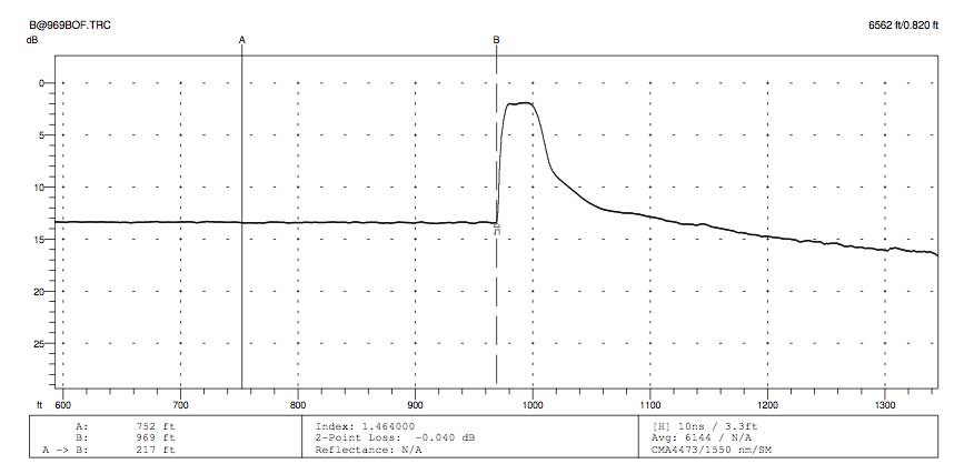
This is a trace of the end of a fiber. Note the
structure in the reflectance peak.
If you expand that peak, you can see structure in it.
That is because the end of the cable has a 10m
patchcord attached. It is too
short to be resolved by the OTDR, so the peak you see
is the merger of two peaks separated by 10m. The
drawing below shows
what happens when two events are too close for the
OTDR to resolve.
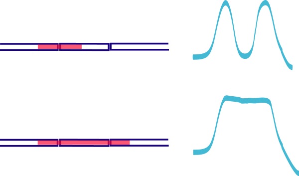
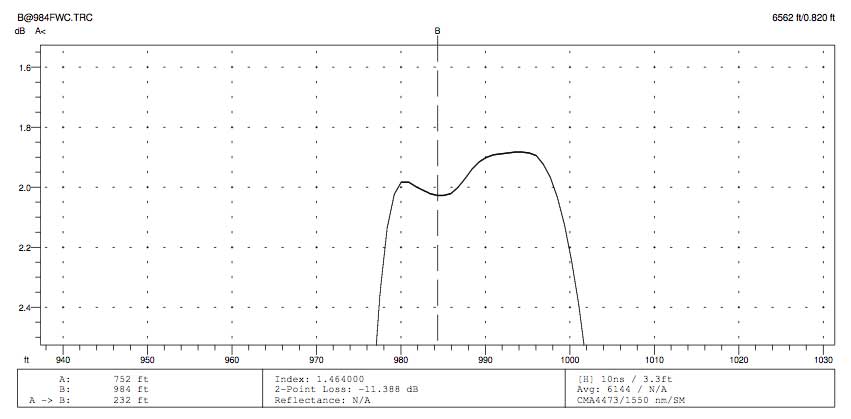
This is the same peak without the 10m patchcord. You
can see there is no structure in the peak.
How are OTDRs
Calibrated?
- Calibration of
OTDRs is a messy issue. There are many variables.
You can purchase OTDR calibration artifacts for
calibrating your OTDR but as far as I know, they are
generally not traceable to national standards labs.
Using fibers to calibrate an OTDR introduces errors.
Two parameters of the OTDR need calibration: dB and
length.
Calibration of the dB scale, used for measuring loss and
attenuation coefficient (which is also dependent on
length calibration) is complicated by the way the
instrument is used. For loss, the measurement is very
low in magnitude (~0.1dB) but fine in resolution (as low
as 0.001dB), so nonlinearities on a small scale along
the entire measurement range are the issue. Proper
calibration would include the linearity of the entire
measurement range which is virtually unknown.
For attenuation coefficient, the dB measurement is over
a longer range and can be done with a calibrated
artifact. But that calibration is wavelength dependent.
For length, it's a matter of time measurement in the
OTDR - distance is calibrated from the index of
refraction of the fiber or the group velocity of the
test pulse in the fiber. This can be done with a
calibration artifact - a fiber of known length and index
of refraction - but again the calibration is wavelength
sensitive.
You can get calibration artifacts from NPL in the UK,
but you need to know the calibration wavelength of your
OTDR and the characteristics of their artifact to make
corrections.
Another method uses a electronic calibrator - take the
pulse from the OTDR and trigger a delayed return pulse
to calibrate the distance scale and a optical ramp to
simulate the attenuation of a fiber. This removes the
unknowns associated with using a fiber and has been
championed by many scientific types.
Any OTDR manufacturers want to offer their wisdom?
Our thanks to FOA
Master instructor Terry O’Malley (
http://www.fiberopticsolutions.biz/)
for his advice and work creating the sample traces and
the following exercise.
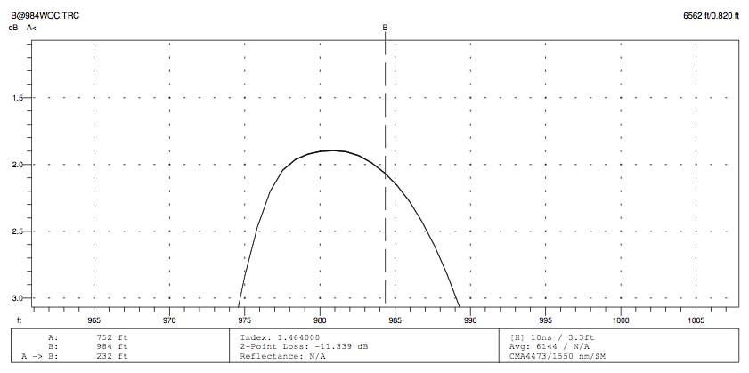
Demonstrating OTDR Length
Measurement Capability
This testing exercise demonstrates that the OTDR is
extremely accurate “unto itself”. That is; not in actual
fiber length (IOR dependent) and defiantly not in sheath
length but it has some important usage when it comes to
troubleshooting.
OTDR GNNettest 4000
Settings
Range 6kft
IOR 1.464
PW 10ns
Fiber Sections
Reel 1= <600 ft.
Reel 2= >1000 ft.
Reel 3= <1000 ft.
TEST 1 & 2
When the reels are connected consecutively (1-2-3) the
distance to the end Fresnel is within two (2) feet from
either direction. Demonstrates the repeatability of distance
measurements.
TEST 3
All three sections of fiber measured exactly the same length
from both ends.
Demonstrates the repeatability of distance measurements.
TEST 4
Cutting off the far end fiber in 1 inch sections. On the
third 1 inch cut off ( a total of 3 inches) the frenel
jumped back towards the OTDR test end one foot. On the
second set of fiber cuts it required 8 one (1 ) inch cuts to
get “behind” a sampling point to again move the Fresnel back
one sampling point in distance.
This demonstrates the resolution as it relates to sampling
points and distance accuracy.
TEST 5
A ten (10) foot cords was attached to the far end and the
distance reading to the far end remained the same as in test
1.
This demonstrates that the 10 foot cord was “hidden” in the
recovery of fiber reel 3’s end termini reflectance.
TEST 6
The 10 foot cord was then connected to the OTDR test cord at
the near end. The system under test measured an additional
10ft exactly.
This demonstrates that the 10 foot cord length could be
measured if not hidden in the end reflectance.
Do Multimode Fibers Show
Gainers Also?
Yes they can. One way it happens is with a mix of regular
and bend-insensitive MM fibers. One cable lab shared
with us a pair of very interesting OTDR traces of what an
OTDR shows on a splice between BIMMF and regular MMF (see
below). Who would have guessed that MMF could show such a
gainer! This is just another proof that OTDR tests are NOT
indicative of actual cable plant performance!
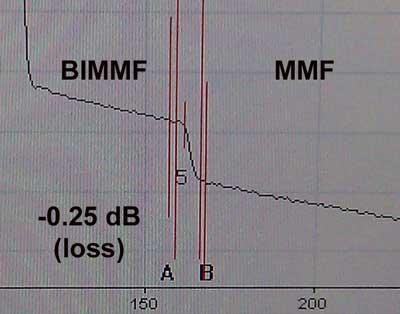
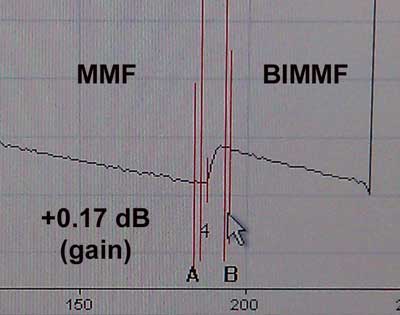
OTDR
traces of a joint between BIMMF and regular MMF. The
higher scattering of the BIMMF causes a big “gainer” in the
reverse direction, illustrating why OTDRs should not be used
to test cable plant loss. If you tested the end-to-end loss
of this link with an OTDR in one direction only, the loss
would have been 0.42 dB different than in the other
direction. If you averaged the two per normal OTDR practice,
the loss would be 0.04 dB, but with a backscatter gain of
0.21 dB, what loss is real with these two fibers?
Finding
Cable Kinks Or Stress Points With An OTDR
One of
the classic reasons to use an OTDR is its ability to find
kinks in a cable or other areas where stress on the cable
will cause high loss. To illustrate this, we set up the FOA
Yokogawa OTDR (thanks again for the donation to the folks at
Yokogawa) with some SM cables and created these traces. The
cable shown is a 60m simplex cable.
First, here is a trace taken before inserting the "kink" at
1550nm. We used 1550nm because stress on the cable causes
more loss at longer wavelengths.
Notice how the reflective connectors cause a 20m+ dead zone
after the connection to the launch cable. To insert the kink
we put in a single bend with a bend radius of ~10mm and
clamped the cable to hold the bend. Then we got this trace:

Now you can see the kink at the halfway point in the cable,
a loss of 2dB. Note there is no reflectance peak, just a
sharp drop off on the trace. A kink tends to look just like
a fusion splice because of the lack of reflection that is
common with a connector.
How do we know it's a kink and not a splice? We can test it
again at 1310nm where the loss at the kink should be less.
Here is the trace at 1310nm:
As you can see, there no indication of a problem at the
lower wavelength. This illustrates that 1) the loss of the
kink is higher at longer wavelengths (it would have been
more loss if we had a 1625nm module for the OTDR) and 2) if
you are looking for stress caused by installation, you need
to use the longest wavelength available - 1550 or 1625nm for
SM, 1300nm for MM.
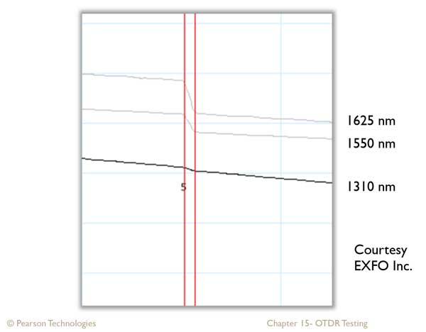
Here is a comparison from an EXFO OTDR furnished by Eric
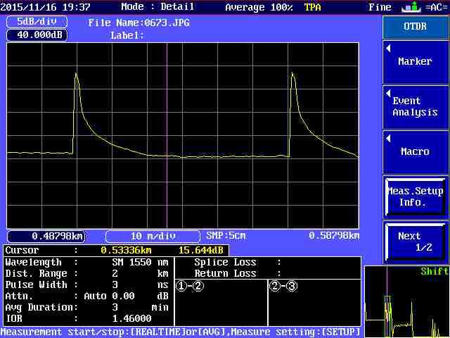
Pearson.
Measuring
Reflectance And Optical Return Loss
Reflectance
In
an OTDR, the peak that identifies a reflective event is
measured and reflectance calculated. Higher peaks
indicate higher reflectance. In order to measure
reflectance, the peak must not saturate the OTDR receiver,
indicated by a flat-topped
reflectance peak (below.) For instance this is an OTDR trace
where reflectance cannot be accurately measured. It will
only indicate a
value less than actual.
Calculating
reflectance in an OTDR is a complicated process involving
the baseline
of the OTDR, backscatter level and power in the reflected
peak as shown in the diagram below. Since reflectance is
defined as a fraction of the power in the test signal, the
OTDR must calculate the test power from the backscatter
level of the fiber, based on the typical backscatter
coefficient of the fiber being tested.
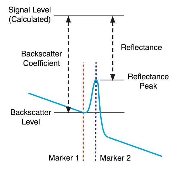
The OTDR measures the backscatter level just before the peak
being measured, applies a correction for the pulse width of
the OTDR test pulse, then calculates the test signal level.
It then measures the power of the reflectance peak and
calculates the reflectance. The indirect way this is
measured causes reflectance measurements with an OTDR have a
fairly high measurement
uncertainty, but have the advantage of showing where
reflective events
are located so they can be corrected if necessary. By
choosing the
reflectance measurement and putting the right (blue) cursor
on the peak
of the reflection and the left (red) cursor just to the left
of the
reflection, the OTDR will measure the reflectance.
Optical
Return Loss (ORL)
The OTDR generally tests ORL by calculating the total all
the light reflected from reflective events plus the total
backscatter from the entire length of fiber being tested.
This ORL measurement is sometimes used as a specification
for very high speed systems as ORL can be a contributor to
noise in a transmission link. It is not a reflectance test
of an individual event and should not be confused with that
test.
- Want
to learn more? Try the FOA
Self-Study Program on OTDRs at Fiber
U.
- Return
To The FOA OTDR Tutorial
- Download the
free FOA OTDR PC
Simulator To Learn How To Use An OTDR
- See
the FOA Virtual Hands-On OTDR Tutorial
- Return
to the FOA Online Reference Guide Table of Contents
Return
to the FOA Guide Table of Contents
Return
to the FOA home page
|