Mechanical Splices
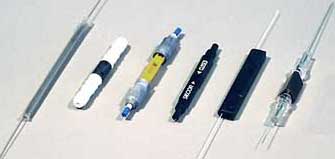
Splices, from left, fusion splice, Elastomeric,
Ultrasplice, Camlock, FiberLok, AT&T Rotary Splice
Mechanical
splices are used to create permanent joints between
two fibers by
holding the fibers in an alignment fixture and
reducing loss and
reflectance with a transparent gel or optical adhesive
between the
fibers that matches the optical properties of the
glass. Mechanical
splices generally have higher loss and greater
reflectance than fusion
splices, and because the fibers are crimped to hold
them in place, do
not have as good fiber retention or pull-out strength.
The splice
component itself, which includes a precision alignment
mechanism, is
more expensive than the simple protection sleeve
needed by a fusion
splice.
Mechanical splices are most popular for fast,
temporary
restoration or for splicing multimode fibers in a
premises
installation. They are also used - without crimping
the fibers - as
temporary splices for testing bare fibers with OTDRs
or OLTSs. Of
course most prepolished
splice connectors
use an internal mechanical splice (several actually
have fusion
splices) so the mechanisms and techniques described
here apply to those
also.
The advantage of mechanical splices is they do not
need an
expensive machine to make the splices. A relatively
simple cleaver and
some cable preparation tools are all that's needed,
although a visual
fault locator (VFL) is useful to optimize some types
of splices.
Alignment Mechanisms
The biggest difference between mechanical splices is
the way the fibers are aligned. Here are some typical
methods.
Capillary Tube
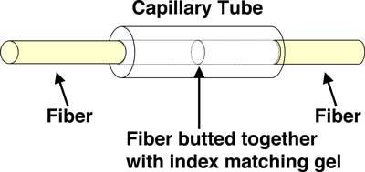
The
simplest method of making a mechanical splice is to
align two fibers in
a small glass tube with a hole just slightly larger
than the outside
diameter of the fibers. This type of splice works well
with UV-cured
adhesive as well as index-matching gel between the
fibers. The
Ultrasplice is a capillary splice.
V-Groove
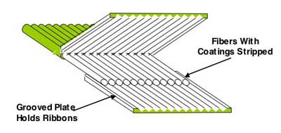
V-groove
splices are quite simple and work well. They work for
single fibers or
even for fiber ribbons as shown here. The Grooved
alignment plates can
be made of many types of materials and are quite
inexpensive.
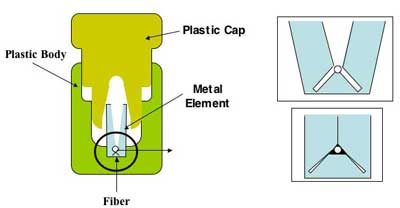
The
3M Fiberlok is a version of a V-groove splice that
uses a metal
stamping inside a plastic case to both align fibers
and crimp them.
It's elegant design and good performance has made it
one of the most
popular mechanical splices.
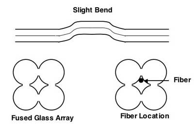
This
method has a more complex alignment mechanism, made
from four small
glass rods fused together with a bend in the middle.
The fibers follow
the grooves made by the joint of two rods. The
complexity and expense
of this, especially compared to a simple V-groove,
limited its use.
Elastomeric
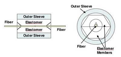
The
GTE Elastomeric splice (still available from Corning)
uses soft
elastomers to hold the fibers in position. It's
similar to a v-groove,
but the grooves are soft so they accomodate slight
variations in fiber
diameter easily.
Rotary Splice
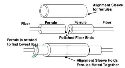
The
AT&T Rotary splice was more like a connector. The
fibers were glued
into glass ferrules and polished. They were then
inserted into an
alignment sleeve and rotated until the lowest loss was
obtained. Again,
complexity and cost, plus labor required, limited
their popularity.
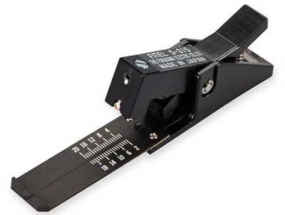
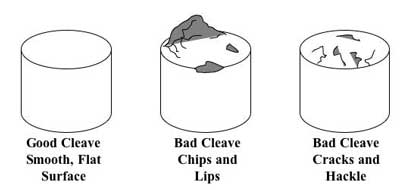
Cleaving Is Important
The
most important step in mechanical splicing is cleaving
the fiber
properly. Most mechanical splicing kits come with an
inexpensive
cleaver that looks like a stapler.
While
this cleaver can produce acceptable results, its
operation requires
some practice and consistent use. The same can be said
of all
inexpensive hand-held cleavers. A better choice is one
of the more
expensive cleavers used for fusion splicers. It is
more expensive but
will usually pay back its cost quickly in higher
yield.
It is
helpful to have a microscope capable of inspecting
fiber ends after
cleaving to determine if the cleave will yield good
splices. Here are
examples of good and bad cleaves.
Mechanical Splicing Process
Cable and fiber preparation is practically the
same as for fusion splicing.
Prepare the cables to be
spliced (VHO
on cable preparation)
Strip jacket,
removing an adequate amount of jacket, usually 2-3 m,
for splicing and
dressing the buffer tubes and fibers in the splice
closure. Leave the
proper amount of strength members to attach the cable
to the closure.
Refer to the splice closure directions for lenths
needed. Clean all
water-blocking materials using appropriate cleaners.
Remove
buffer tubes exposing fibers for splicing. Generally
splice closures
will require ~1 m buffer tubes inside the closure to
and ~ 1 m fiber
inside the splice tray. Clean
all water-blocking materials.
Prepare the fibers to be
spliced
The process is the same for all
splice types: strip, clean & cleave.
Each fiber must be cleaned
thoroughly before stripping for splicing.
When ready to splice a fiber, strip off the buffer
coating(s) to expose the proper length of bare fiber.
Clean the fiber with appropriate wipes.
Cleave the fiber using the process appropriate to the
cleaver being used.
Splicing
Insert
the first fiber into the mechanical splice. Most
splices are designed
to limit the depth of the fiber insertion by the
buffer coating on the
fiber.
Clamp the fiber in place if fibers are held
separately. FiberLok splices clamp both fibers at
once.
Repeat these steps for the second fiber.
Optimizing Splices Using A Visual Fault Locator
You
can sometimes improve the loss of a mechanical splice
by gently
withdrawing one of the fibers a slight amount,
rotating it slightly and
reinserting it. It works best with a VFL (visual fault
locator) if the
fiber ends that are being spliced are visible.
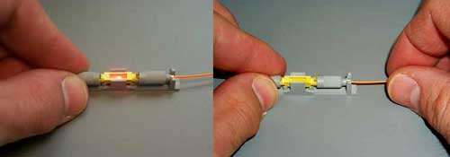
Shine a visual fault locator into the fiber and note
the light loss at the splice (Left in photo).
Pull one fiber out by 1-2 mm (about 1/16 inch.)
Rotate the fiber slightly and reinsert fully.
Keep trying and watch for minimal light (Right in
photo.)
Crimp fiber in place.
Splice Closures
After
fibers are spliced, they
will be placed in a splice tray which is then placed
in an splice
closure. Outside plant closures will be carefully
sealed to prevent
moisture damage to the splices. In premises
applications, some
patch panels have provision for splices in the back,
simplifying their
storage.
All
cables that contain metallic elements like armor or
strength members
must be grounded and bonded at each splice point.
Closures are designed
to clamp cable strength members to provide strength to
prevent pulling
the cable out and seals to prevent moisture damage to
the splices.
Testing
Splices can be used to create long
cable lengths by splicing multiple cable segments.
After splicing, the only way to test it is
with an OTDR.
Since OTDRs have directional errors, testing may be
required from both
directions and averaged. Generally long concatenated
cables are tested
with an OTDR and traces kept for documentation in case
of restoration.
Be aware of the OTDR distance resolution as a
limitation of testing
short premises cables.
Virtual
Hands On, Mechanical Splicing
Videos on mechancial splicing on
the FOA Channel on 
|
