Using
Attenuators With Fiber Optic Data Links
Most of
our attention in a data link focuses on the cable plant, particularly
minimizing the loss of the installed cable plant. However many links
have too much power at the receiver, a consequence of having links
designed for long distances being used at shorter distances. If you are
unfamiliar with datalinks and there performance parameters, we suggest
you refer to the FOA Guide page on datalinks.
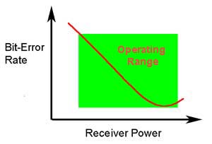
The ability of
any fiber optic system to transmit data ultimately
depends on the optical power at the receiver as shown
above, which shows the data link bit error rate as a
function of optical power at the receiver. (BER is the
inverse of signal-to-noise ratio, e.g. high BER means
poor signal to noise ratio.) Either too little or
too much power will cause high bit error rates.
We refer to the
low power end of the operating range of the receiver as the sensitivity
and the high end as overload. Too much power,
and the receiver amplifier saturates, too little
and
noise becomes a problem as it interferes with
the
signal. This receiver power depends on two basic
factors: how much power is launched into the
fiber by
the transmitter and how much is lost by the loss
in
the optical fiber cable plant that connects the
transmitter and receiver.
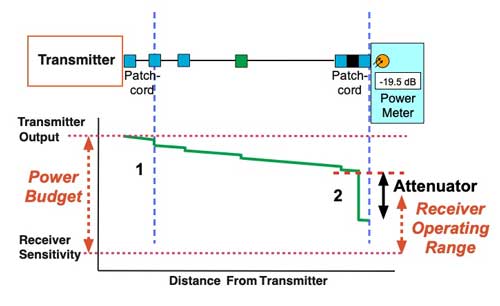
The drawing below
illustrates the power in a operating fiber optic data link. The
transmitter output and the receiver sensitivity determine the Power
Budget. The receiver sensitivity and overload levels determines the
Receiver Operating Range.
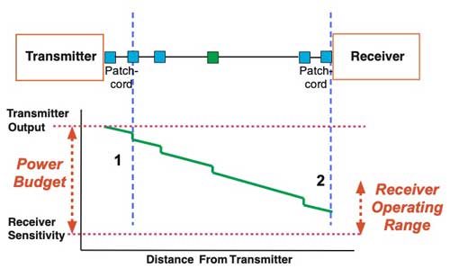
If the optical power at the
receiver is higher than the receiver sensitivity, as shown above, the
difference is the operating "margin" of the system.
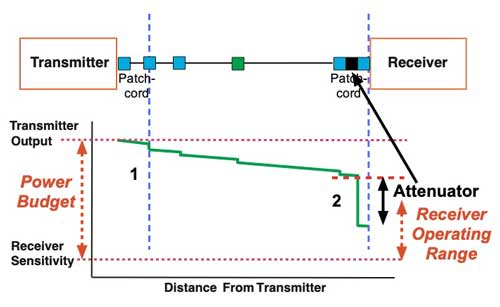
If the receiver power is
too high - that is greater than the upper level
of the receiver operating range (see below) - as it often is in short
singlemode systems with
laser transmitters, you can reduce receiver
power with
an attenuator.
The attenuator should always be placed near the receiver to make it
convenient to measure and adjust the power level at the receiver and it
ensures that any reflectance will not affect the transmitter.
The attenuator should reduce the receiver power to
a level near the middle of the receiver operating range, not too close
to either the sensitivity limit or the overload level. The proper amount
of attenuation needed can be determined during the design stage by
calculating the receiver power from the transmitter output and cable
plant loss budget or after installation by measuring the power at the
receiver with a fiber optic power meter.
Examples With Numbers
To illustrate this, consider a link with these specifications;
Transmitter Output: 0 dBm (This is the minimum power output of
the transmitter. Specs may show a range of power, e.g. +3 to 0 dBm, but
for calculating the power budget, the minimum power is used to be
conservative.)
Receiver Operating Range: -15 to -30 dBm (That means at power
levels above -15 dBm, the receiver will overload and below -30 dBm the
signal to noise (S/N) ration will be low and cause a high
bit-error-rate.)
Receiver Sensitivity: -30 dBm (This is the minimum power in the operating range)
Receiver Overload: -15 dBm (This is the maximum power in the operating range)
The Power Budget is calculated from the transmitter output - (0 dBm) - to the minimum power at the receiver - (- 30 dBm) - is 30 dB. That is the maximum amount of loss in the cable plant that can be tolerated. Maximum!
Since the receiver overloads at -15 dBm and the transmitter output is 0 dBm, the minimum amount of attenuation in the cable plant must be at least 15 dB or the receiver will overload. If the cable plant loss is less than 15 dB, we need an attenuator.
If we have a cable plant with total end-to-end loss is less than 15 dB,
we need to add an attenuator. Actually we might say 20 dB, because we do
not want the receiver to be on the edge of overload - ideally, the
receiver power would be in the range of -20 dBm - and with the
transmitter at 0 dBm, that means the attenuator and the cable plant need
to total 20 dB.
So if the cable plant loss is 10 dB, we need a 10 dB attenuator.
So if the cable plant loss is 15 dB, we should ideally use a 5 dB attenuator.
So if the cable plant loss is 20 dB, we do not need any attenuator.
If the cable plant loss approaches 30 dB or more, we need a more powerful transmitter.
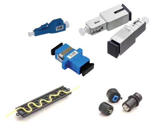
Types Of Attenuators
Attenuators can be made by
introducing an
end gap between two fibers (gap loss), angular
or
lateral misalignment, poor fusion splicing
(deliberately), inserting a neutral density
filter or
even stressing the fiber (usually by a
serpentine holder
or a mandrel wrap). Attenuators are available in
models
with variable attenuation or with fixed values
from a
few dB to 20 dB or more. They may be inline,
plugging into a receiver input or a patch panel near the receiver, a
mating adapter for 2 patchcords or serpentine attenuators that work on
adding stress loss to a patchcord.
Generally,
multimode systems do not need attenuators. Multimode
sources, even VCSELs, rarely have enough power output to
saturate receivers. Singlemode systems, especially short
links, often have too much power and need attenuators.
For a
singlemode applications, especially analog CATV systems,
the most important specification, after the correct loss
value, is return loss or reflectance! Many types of
attenuators (especially gap loss types) suffer from high
reflectance, so they can adversely affect transmitters
just like highly reflective connectors.
Choose a type
of attenuator with good reflectance specifications and
always install the attenuator ( X in the drawing)
as shown at the receiver end of the link. This is
because it's more convenient to test the receiver
power before and after attenuation or while
adjusting it with your power meter at the receiver,
plus any reflectance will be attenuated on its
path back to the source.
Test the system power with the transmitter turned on and
the attenuator installed at the receiver using a fiber
optic power meter set to the system operating
wavelength. Check to see the power is within the
specified range for the receiver.
If the
appropriate attenuator is not available, simply coil
some patchcord around a pencil while measuring power
with your fiber optic power meter, adding turns until
the power is in the right range. Tape the coil and your
system should work. This type of attenuator has no
reflectance and is very low cost! The fiber/cable
manufacturers may worry about the relaibility of a cable
subjected to such a small bend radius. You should
probably replace it with another type of attenuator at
some point, however.
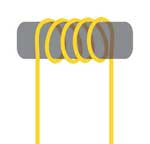
Singlemode attenuator made by wrapping fiber or simplex
cable around a small mandrel. This will not work well
with bend-insensitive
fiber.
Table
of Contents: The FOA Reference Guide To Fiber Optics
