OSP Fiber Optic Transmission Systems
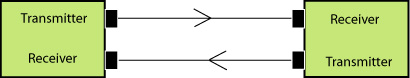
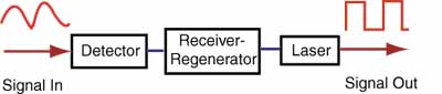
Fiber Optic Datalink
Fiber optic transmission systems all use
data links that work similar to the
diagram shown
above. Each fiber link consists of a transmitter on one end of a fiber
and a
receiver on the other end. Most systems operate by transmitting in one
direction on one fiber and in the reverse direction on another fiber
for full duplex operation. It's possible to transmit both directions on
one fiber but it requires couplers to do so and fiber is less expensive
than couplers. A FTTH passive optical network (PON) is one of the only
systems using bidirectional transmission over a single fiber because
its network architecture is based around couplers already.
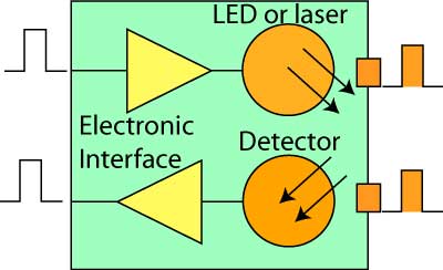
Fiber Optic Transceiver
Most
systems use a "transceiver" which includes both transmission and
receiver in a single module. The transmitter takes an electrical
input and converts it to an optical output from a laser diode
or LED. The light from the transmitter is coupled into the fiber
with a connector and is transmitted through the fiber optic cable
plant. The light from the end of the fiber is coupled to a receiver
where a detector
converts the light into an electrical signal which is then conditioned
properly for use by the receiving equipment.
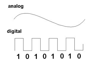
Analog or Digital
Analog
signals are continuously variable signals where the information in the
signal is contained in the amplitude of the signal over time. Digital
signals are sampled at regular time intervals and the amplitude
converted to digital bytes so the information is a digital number.
Analog signals are the natural form of most data, but are subject to
degradation by noise in the transmission system. As an analog signal is
attenuated in a cable, the signal to noise ratio becomes worse so the
quality of the signal degrades. Digital signals can be transmitted long
distances without degradation as the signal is less sensitive to noise.
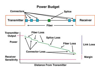
Fiber optic datalinks can be either analog or digital in nature, although most are digital. Both have
some common critical parameters and some major differences. For
both, the optical loss margin or power budget is most important. This is determined
by connecting the link up with an adjustable attenuator in the
cable plant and varying the loss between transmitter and receiver until one can generate the curve
shown above. Analog datalinks will be tested for signal to noise
ratio to determine link margin, while digital links use bit error
rate as a measure of performance. Both links require testing over
the full bandwidth specified for operation, but most data links
are now specified for a specific network application, like AM
CATV or RGB color monitors for analog links and SONET, Ethernet or Fibre Channel for digital links.
Sources for Fiber Optic Transmitters
The
sources used for fiber optic transmitters need to meet several
criteria: it has to be at the correct wavelength, be able to be
modulated fast enough to transmit data and be efficiently coupled into
fiber.
Four types of sources are commonly
used, LEDs, fabry-perot (FP) lasers, distributed feedback (DFB) lasers and vertical cavity surface-emitting
lasers (VCSELs). All convert electrical signals into optical
signals, but are otherwise quite different devices. All three are tiny
semiconductor devices (chips). LEDs and VCSELs are fabricated on
semiconductor wafers such that they emit light from the surface of the
chip, while f-p lasers emit from the side of the chip from a laser
cavity created in the middle of the chip.
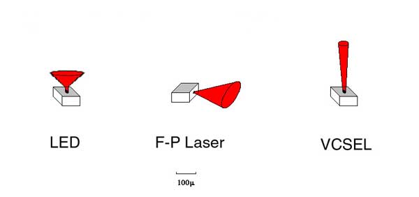
LEDs
have much lower power outputs than lasers and their
larger, diverging light output pattern makes them harder to couple
into fibers, limiting them to use with multimode fibers. Laser have
smaller tighter light outputs and are easily coupled to singlemode
fibers, making them ideal for long distance high speed links. LEDs have
much less bandwidth than lasers and are limited to systems operating up
to about 250 MHz or around 200 Mb/s. Lasers have very high bandwidth
capability, most being useful to well over 10 GHz or 10 Gb/s.
Because of their fabrication methods, LEDs
and VCSELs are cheap to make. Lasers are more expensive because
creating the laser cavity inside the device is more difficult, the chip
must be separated from the semiconductor wafer and each end coated
before the laser can even be tested to see if its good.
Typical Fiber Optic Source Specifications
| Device Type |
Wavelength (nm) |
Power into
Fiber (dBm) |
Bandwidth |
Fiber Types |
| LED |
850, 1300 |
-30 to -10 |
<250 MHz |
MM |
| Fabry-Perot Laser |
850,
1310 (1280-1330) 1550 (1480-1650) |
0 to +10 |
>10 GHz |
MM, SM |
| DFB Laser |
1550 (1480-1650) |
0 to +25 |
>10 GHz |
SM |
| VCSEL |
850 |
-10 to 0 |
>10 GHz |
MM |
LEDs
have a limited bandwidth while all types of lasers are very fast.
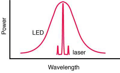
Another big difference between LEDs and both types of lasers is the
spectral output. LEDs have a very broad spectral output which causes
them to suffer chromatic dispersion in fiber, while lasers have a
narrow spectral output that suffers very little chromatic dispersion. DFB lasers, which are used in long distance and DWDM systems, have the narrowest spectral width which minimizes chromatic dispersion on the longest links. DFB lasers are also
highly linear (that is the light output directly follows the electrical
input) so they can be used as sources in AM CATV systems.
The
choice of these devices is determined mainly by speed and fiber
compatibility issues. As many premises systems using multimode
fiber have exceeded bit rates of 1 Gb/s, lasers (mostly VCSELs) have
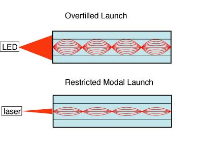
replaced LEDs. The output of the LED is very broad but lasers are
very focused, and the sources will have very different modal fill in
the fibers. The restricted launch of the VCSEL (or any laser) makes the effective
bandwidth of the fiber higher, but laser-optimized fiber, usually OM3,
is the choice for lasers.
The
electronics for a transmitter are simple. They convert an incoming
pulse (voltage) into a precise current pulse to drive the source.
Lasers generally are biased with a low DC current and modulated above
that bias current to maximize speed.
Detectors for Fiber Optic Receivers
Receivers
use semiconductor detectors (photodiodes or photodetectors) to convert
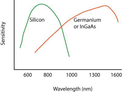
optical signals to electrical signals. Silicon photodiodes
are used for short wavelength links (650 for POF and 850 for glass MM
fiber). Long wavelength systems usually use InGaAs (indium gallium
arsenide) detectors as they have lower noise than germanium which
allows for more sensitive receivers.
Very high speed systems sometimes use avalanche photodiodes (APDs) that are biased at high voltage to create gain in the photodiode. These devices are more expensive and more complicated to use but offer significant gains in performance.
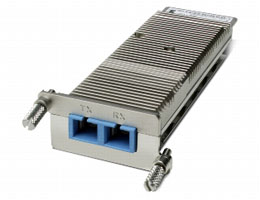
Packaging
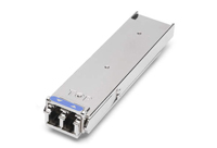
Transcivers
are usually packaged in industry standard packages like these XFP
modules for gigabit datalinks(L) and Xenpak (R). The XFP modules
connect to a duplex LC connector on the optical end and a standard
electrical interface on the other end. The Xenpak are for 10 gigabit
networks but use SC duplex connection. Both are similar to media converters but are powered from the equipment they are built into.
Performance
Just
as with copper
wire or radio transmission, the performance of the fiber optic
data link can be determined by how well the reconverted electrical
signal out of the receiver matches the input to the transmitter.
The discussion of performance on datalinks applies directly to
transceivers which supply the optical to electrical conversion.
Every
manufacturer of transcivers specifies
their product for receiver sensitivity (perhaps a minimum power
required)
and minimum power coupled into the fiber from the source. Those
specifications will end up being the datalink specifications on the
final product used in the field.
Wavelength
Division Multiplexing
(WDM)
Why Is WDM Used?
With the exponential growth in communications, caused mainly by
the wide acceptance of the Internet, many carriers are finding
that their estimates of fiber needs have been highly underestimated.
Although most cables included many spare fibers when installed,
this growth has used many of them and new capacity is needed.
Three methods exist for expanding capacity: 1) installing more
cables, 2) increasing system bitrate to multiplex more signals
or 3) wavelength division multiplexing.
Installing more cables will be the preferred method in many cases,
especially in metropolitan areas, since fiber has become incredibly
inexpensive and installation methods more efficient (like mass
fusion splicing.) But if conduit space is not available or major
construction is necessary, this may not be the most cost effective.
Increasing system bitrate may not prove cost effective either.
Many systems are already running at SONET OC-48 rates (2.5 GB/s)
and upgrading to OC-192 (10 GB/s) is expensive, requires changing
out all the electronics in a network, and adds 4 times the capacity,
more than may be necessary.
The third alternative, wavelength division multiplexing (WDM),
has proven more cost effective in many instances. It allows using
current electronics and current fibers, but simply shares fibers
by transmitting different channels at different wavelengths (colors)
of light. Systems that already use fiber optic amplifiers as repeaters
also do not require upgrading for most WDM systems.
How Does WDM Work?
It is easy to understand WDM. Consider the fact that you can see
many different colors of light - reg, green, yellow, blue, etc.
all at once. The colors are transmitted through the air together
and may mix, but they can be easily separated using a simple device
like a prism, just like we separate the "white" light
from the sun into a spectrum of colors with the prism.
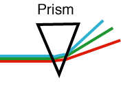
Separating a beam of
light into
its colors
This technique was first
demonstrated with
optical fiber in the early 80s when telco fiber optic links still
used multimode fiber. Light at 850 nm and 1300 nm was injected
into the fiber at one end using a simple fused coupler. At the
far end of the fiber, another coupler split the light into two
fibers, one sent to a silicon detector more sensitive to 850 nm
and one to a germanium or InGaAs detector more sensitive to 1300
nm. Filters removed the unwanted wavelengths, so each detector
then was able to receive only the signal intended for it.
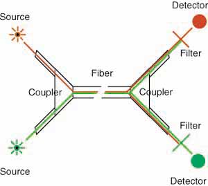
WDM with couplers
and filters
By the late 80s, all telecom
links were
singlemode fiber, and coupler manufactures learned how to make
fused couplers that could separate 1300nm and 1550 nm signals
adequately to allow WDM with simple, inexpensive components. However,
these had limited usefulness, as fiber was designed differently
for 1300nm and 1550 nm, due to the dispersion characteristics
of glass. Fiber optimized at 1300 nm was used for local loop links,
while long haul and submarine cables used dispersion-shifted fiber
optimized for performance at 1550 nm. This simple version of WDM is
widely used in fiber to the home (FTTH) applications. Signals are sent
downstream to the subscriber at 1490 nm (and 1550 for analog CATV if
used) and upstream at 1310 n.
With the advent of fiber optic amplifiers for repeaters in the
late 80s (see below), emphasis shifted to the 1550 nm transmission band. WDM
only made sense if the multiplexed wavelengths were in the region
of the fiber amplifiers operating range of 1520 to 1560 nm. It
was not long before WDM equipment was able to put 4 signals into
this band, with wavelengths about 10 nm apart.
The input end of a WDM system is really quite simple. It is a
simple coupler that combines all the inputs into one output fiber.
These have been available for many years, offering 2, 4, 8, 16,
32 or even 64 inputs. It is the demultiplexer that is the difficult
component to make.
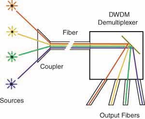
WDM demultiplexer
The demultiplexer takes the
input fiber
and collimates the light into a narrow, parallel beam of light.
It shines on a grating (a mirror like device that works like a
prism, similar to the data side of a CD) which separates the light
into the different wavelengths by sending them off at different
angles. Optics capture each wavelength and focuses it into a fiber,
creating separate outputs for each separate wavelength of light.
DWDM
Current systems offer from 4 to 32 channels of wavelengths. The
higher numbers of wavelengths has lead to the name Dense Wavelength
Division Multiplexing or DWDM. The technical requirement is only
that the lasers be of very specific wavelengths and the wavelengths
are very stable, and the DWDM demultiplexers capable of distinguishing
each wavelength without crosstalk.
CWDM
Coarse
wavelength-division multiplexing is another variant of WDM. Generally
CWDM refers to using lasers spaced 20 nm apart over the full range of
1260 to 1670 nm. It only works on low water peak fibers, where the high
water absorption bands have been eliminated in the manufacture of the
fiber.
Advantages of WDM
A WDM system has some features that make them very useable. Each
wavelength can be from a normal link, for example a OC-48 link,
so you do not obsolete most of your current equipment. You merely
need laser transmitterss chosen for wavelengths that match the
WDM demultiplexer to make sure each channel is properly decoded
at the receiving end.
If you use an OC-48 SONET input, you can have 4X2.5 GB/s = 10
GB/s up to 32 X 2.5 GB/s = 80 GB/s. While 32 channels are the
maximum today, future enhancements are expected to offer 80-128
channels!
And you are not limited to SONET, you can use Gigabit Ethernet
for example, or you can mix and match SONET and Gigabit Ethernet
or any other digital signals! You can even mix in analog channels like
CATV, as is done with BPON FTTH systems.
Signal Regernators
Repeaters
Another technology that facilitates DWDM is the development of
fiber optic amplifiers
for use as repeaters.
They can amplify numerous wavelengths of light simultaneously,
as long as all are in the wavelength range of the FO amplifier.
They work best in the range of 1520-1560 nm, so most DWDM systems
are designed for that range. Now that fiber has been made with
less effect from the OH absorption bands at 1400 nm and 1600 nm,
the possible range of DWDM has broadened considerably. Technology
needs development for wider range fiber amplifiers to take advantage
of the new fibers.
Fiber
Amplifiers
While the low loss of optical
fiber allows
signals to travel hundreds of kilometers, extremely long haul
lines and submarine cables require regenerators or repeaters to
amplify the signal periodically. In the beginning, repeaters basically
consisted of a receiver followed by a transmitter. The incoming
signal was converted from a light signal to an electrical signal
by a receiver, cleaned up to remove as much noise as possible,
then was retransmitted by another laser transmitter.
Electronic Repeater
These repeaters added noise to
the signal,
consumed much power and were complicated, which means they were
a source of failure. They also had to be made for the specific
bit rate of transmission and upgrading required replacing all
the repeaters, a really difficult task in an undersea cable!
Since the 1960s, researchers knew how to make fiber lasers. Proper
doping of the fiber (introducing small amounts of active elements
into the glass fiber) allowed it to be pumped with external light
sources until stimulated emission occurred. While making fiber
amplifiers was hypothesized early in the stages of fiber optic
development, it was not until 1987 that working models were realized.
Major contributors to the development included Bell Labs and NTT.
The typical fiber amplifier works in the 1550 nm band and consists
of a length of fiber doped with Erbium pumped with a laser at
980. The pump laser supplies the energy for the amplifier, while
the incoming signal stimulates emission as the pulse passes through
the doped fiber. The stimulated emission stimulates more emission,
so there is a rapid, exponential growth of photons in the doped
fiber. Gains of >40 dB (10,000X) are possible with power outputs
>+20 dBm (100 mW).
Basic Fiber Amplifier
To date, the most efficient
fiber amplifiers
have been Erbium-Doped Fiber Amplifiers (EDFAs) operating in the
1550 nm range. Since most systems still work at 1310 nm, considerable
research has been done to find materials that would work in this
range. Praseodymium-doped fluoride fiber amplifiers (PDFFAs) using
fibers made from zirconium fluoride or hafnium fluoride have shown
some promise, but have not developed the performance needed for
widespread applications.
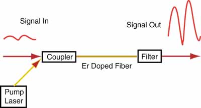
The basic structure of an EDFA is very simple. The amplifier itself
emits light energy in a signal wavelength (usually about 1540nm)
using energy supplied to it by photons in a pump wavelength (usually
980nm) when stimulated by incoming photons in the signal - the
signal which needs amplification. Just like in a laser, the emitted
photons then stimulate other emissions, so there is an exponential
growth of photons. Supporting the amplifier is a pump laser, which
supplies the amplifier's energy, a coupler, which combines the
pump laser beams and the signal laser beam and puts them on a
single fiber, and an optical filter, which removes the remaining
traces of the pump beam so that it doesn't interfere with reception
of the signal.
Alternative Designs
The simple diagram of an EDFA shown above is not the only
way EDFAs can be made. Pumping can be done in a forward direction
as shown, backward from the output end or in both directions.
Optical isolators are commonly used at both ends of the EDFA to
prevent pump energy from escaping back down the fiber or unwanted
reflections that may affect laser stability. Filters, often Bragg
gratings (filters fabricated in fibers), are used to flatten the
gain over the broadest wavelength range for use in WDM systems.
- Other Applications
- Besides being used as
repeaters, fiber amplifiers are used to increase signal level for CATV
systems, which require high power levels at the receiver to maintain
adequate signal to noise performance, allowing longer cable runs or
using splitters to "broadcast" a single signal through a coupler to
many fibers, saving the cost of additional transmitters. In telephony,
they combine with DWDM
(dense wavelength division multiplexers) to overcome the inefficiencies
of DWDMs for long haul transmission.
Future Developments
Fiber amplifiers continue to be developed to support Dense Wavelength
Division Multiplexing and to expand to the other wavelength bands
supported by fiber optics. Now that fiber manufacturers have all
but removed the water bands from the spectrum, there is now a
range of 1260 to 1610 nm available for use. Fiber amplifiers and
diode lasers will probably be developed within this band to completely
fill it with useable bandwidth.
Applications
Two obvious applications are already in use, submarine cables
and extending the lifetime of cables where all fibers are being
used. For submarine cables, DWDM enhances the capacity without
adding fibers, which create larger cables and bulkier and more
complicated repeaters. Adding service in areas where cables are
now full is another good application.
But this technology may also reduce the cost on all land-based
long distance communications links and new technology may lead
to totally new network architectures.
Further Enhancements
Imagine an all-optical network that uses DWDM, switches signals
in the optical domain without converting signals to electronics,
and can add or drop signals by inserting or withdrawing wavelengths
at will. All this is being researched right now, and given the
speed with which optical technology advances, an all-optical network
may not be far in the future!
Fiber Optic Network Optical Wavelength Transmission Bands
As
fiber optic networks have developed for longer distances, higher speeds
and wavelength-division multiplexing (WDM), fibers have been used in
new wavelength ranges, now called "bands," where fiber and transmission
equipment can operate more efficiently. Singlemode fiber transmission
began in the "O-band" just above the cutoff wavelength of the SM fiber
developed to take advantage of the lower loss of the glass fiber at
longer wavelengths and availablility of 1310 nm diode lasers.
(Originally SM fibers were developed for 850 nm lasers where the fiber
core was about half what it is for today's conventional SM fiber (5
microns as opposed to 8-9 microns at 1310 nm.)
To take advantage of the lower loss at 1550 nm, fiber was developed for the C-band. As links became longer and fiber amplifiers began being used instead of optical-to-electronic-to-optical repeaters, the C-band became more important. With the advent of DWDM
(dense wavelength-division multiplexing) which allowed multiple signals
to share a single fiber, use of this band was expanded. Development of
new fiber amplifiers (Raman and thullium-doped) promise to expand DWDM
upward to the L-band.
Since the fiber manufacturers have been able to reduce the water peaks at 1244 and 1383 nm to very low levels, several
low-cost versions of WDM are in use,
generally referred to as Coarse WDM or CWDM. Most do not work over long
distances so do not require amplification, broading the wavelength
choice. The most popular is FTTH PON systems, sending signals
downstream to users at 1490 nm and using low cost 1310 nm transmission
upstream. Early PON systems also use 1550 downstream for TV, but that
is being replaced by IPTV on the downstream digital signal at 1490 nm.
Other systems use a combination of S, C and L bands to carry signals
because of the lower attenuation of the fiber. Some systems even use
lasers at 20 nm spacings over the complete range of 1260 to 1660 nm but
only with low water peak fibers.
Manufacturers have
been able to make fiber with low-water peaks, opening up a new
transmission band (E-band), but it has not yet proven useful except for CWDM. It is
probably mostly useful as an extension of the O-band but few
applications have been proposed and it is very energy-intensive for
manufacture.
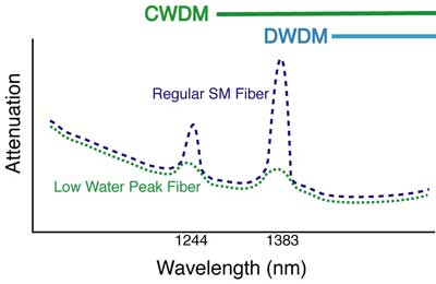
Low Water Peak Fiber
Wavelength Bands Used For Fiber Optic Transmission Systems
| Band Name |
Wavelengths |
Description |
| O-band |
1260 – 1360 nm |
Original band, PON upstream, low end of CWDM systems |
| E-band |
1360 – 1460 nm |
Water peak band |
| S-band |
1460 – 1530 nm |
PON downstream |
| C-band |
1530 – 1565 nm |
Lowest attenuation, original DWDM band, compatible with fiber amplifiers, CATV |
| L-band |
1565 – 1625 nm |
Low attenuation, expanded DWDM band |
| U-band |
1625 – 1675 nm |
|
|
|
|
Datalink Performance
Just as with copper
wire or radio transmission, the performance of the fiber optic
data link can be determined by how well the reconverted electrical
signal out of the receiver matches the input to the transmitter.
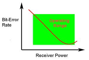
The ability of any fiber optic system to
transmit data ultimately
depends on the optical power at the receiver as shown above, which
shows the data link bit error rate as a function of optical power
at the receiver. (BER is the inverse of signal-to-noise ratio, e.g.
high BER means poor signal to noise ratio.) Either too little or
too much power will cause
high bit error rates. Too much power, and the receiver amplifier
saturates, too little and noise becomes a problem as it interferes with
the signal. This receiver
power depends on two basic factors: how much power is launched
into the fiber by the transmitter and how much is lost by attenuation
in the optical fiber cable plant that connects the transmitter and
receiver.
The optical power budget of the link is determined by two factors,
the sensitivity of the receiver, which is determined in the bit
error rate curve above and the output power of the transmitter
into the fiber. The minimum power level that produces an acceptable
bit error rate determines the sensitivity the receiver. The power
from the transmitter coupled into the optical fiber determines
the transmitted power. The difference between these two power
levels determines the loss margin (power budget) of the link.
High speed
links like gigabit or 10gigabit Ethernet LANs on multimode fiber have
derating factors for the bandwidth of fiber caused by dispersion spreading out the data pulse. Older 62.5/125 OM1 fiber
will generally operate only on shorter links while links on 50/125 OM3
laser-optimized fiber will go the longest distance. Even long distance
singlemode fiber links may have limitations caused by chromatic or
polarization-mode dispersion.
If the link is
designed to operate at differing bit rates, it is necessary to
generate the performance curve for each bit-rate. Since the total
power in the signal is a function of pulse width and pulse width
will vary with bit-rate (higher bit-rates means shorter pulses),
the receiver sensitivity will degrade at higher bit-rates.
Every manufacturer of datalinks components and systems specifies
their link for receiver sensitivity (perhaps a minimum power required)
and minimum power coupled into the fiber from the source. Typical
values for these parameters are shown in the table below. In order for a manufacturer or system designer to
test them properly, it is necessary to know the test conditions.
For data link components, that includes input data frequency or bitrate
and duty cycle, power supply voltages and the type of fiber coupled
to the source. For systems, it will be the diagnostic software
needed by the system.
Typical Fiber optic link/system performance parameters
| Link type |
Source/Fiber Type |
Wave-
length (nm)
|
Transmit Power (dBm) |
Receiver Sen- sitivity (dBm) |
Margin (dB) |
| Telecom |
laser/SM |
1300/1550 |
+3 to -6 |
-30 to -45 |
30 to 40 |
|
DWDM |
1550 |
+20 to 0 |
-30 to -45 |
40 to 50 |
| Datacom |
LED/VCSEL |
850 |
-3 to -15 |
-15 to -30 |
3 to 25 |
|
LED/laser |
1300 |
-0 to -20 |
-15 to -30 |
10 to 25 |
| CATV(AM) |
laser/SM |
1300/1550 |
+10 to 0 |
0 to -10 |
10 to 20 |
Within the world of datacommunications links and networks, there are
many vendor-specific fiber optic systems, but there are also a
number of industry standard networks such as Ethernet which have fiber optic standards. These networks have agreed
upon specifications common to all manufacturers' products to insure
interoperability. This page in FOA Tech Topics shows a summary of specifications for many of these systems.
Long Distance Considerations
Fiber
optic links can now be hundreds or even thousands of kilometers long
and operate at 10 gigabits per second or more – certainly lots more in
the future – and at many wavelengths over a single fiber. Problems that
are ignorable on short or metropolitan links may become extremely
important on long links. The section on optical fiber
will cover topics like chromatic dispersion, polarization mode
dispersion and spectral attenuation that can be important in these long
links.
Summary
Datalinks must have proper receiver power, neither too little
nor too much, for proper operation.
The link margin can be measured with a power meter and variable
attenuator.
Test Your Comprehension
References
The FOA Reference Guide to Outside Plant Fiber Optics
The FOA Online Reference Guide to Fiber Optics
You can buy the printed version of the The FOA Reference Guide to Outside Plant Fiber Optics from the FOA eStore or Amazon.
Table of Contents: The FOA Reference Guide To Fiber Optics