Fiber To The Home
Architectures
New network
architectures have been developed to reduce the cost of
installing high bandwidth services to the home, often
lumped into the acronym FTTx for "fiber to the x". These
include FTTC for fiber to the curb, also called FTTN or
fiber to the node, FTTH for fiber to the home and FTTP for
fiber to the premises, using "premises" to include homes,
apartments, condos, small businesses, etc. Recently, we've
even added FTTW for fiber to wireless.
Let's begin by describing
these network architectures.
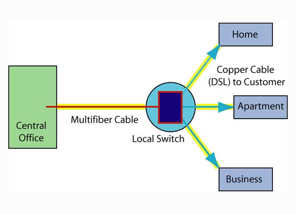
FTTC:
Fiber To The Curb (or Node, FTTN)
Fiber to the
curb brings fiber to the curb, or just down the street,
close enough for the copper wiring already connecting the
home to carry DSL (digital subscriber line, or fast
digital signals on copper.)
FTTC bandwidth depends on DSL performance where the
bandwidth declines over long lengths from the node to the
home. There are many types of DSL (ADSL, HDSL, RADSL,
VDSL, UDSL, etc. - over 22 varieties) that offer varying
performance over length, including some which "bond" more
pairs of wires to improve the bandwidth.
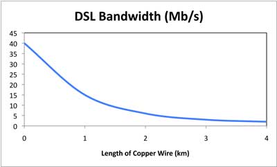
Newer homes that have good copper and are near the DSL
switch can expect good service up to about 20Mb/s. Homes
with older copper or longer distances away will have less
available bandwidth.
FTTC is less expensive than FTTH when first
installed, but since performance depends on the quality of
the copper wiring currently installed to the home and the
length to reach from the node to the home, the level of
service may be obsoleted quickly by customer demands. In
older areas where the copper wires are of poorer quality
or have degraded over time, DSL is difficult or impossible
to implement and very expensive to maintain.
While there are still many DSL
subscribers, by 2020 service providers basically abandoned
it as obsolete. Now some large service providers who offer
both landline and wireless are proposing using 5G wireless
for the drop to the home. See below.
FTTW: Fiber to Wireless
Of course today's mobile device users depend
on wireless connections for their laptops, smartphones and
tablets. Even many homes and businesses are now using
wireless connectivity, especially those outside areas
where FTTH or FTTC are not available or considered
economical for future installations. Options for wireless
include cellular systems which are the most widely
available wireless solution around the world,
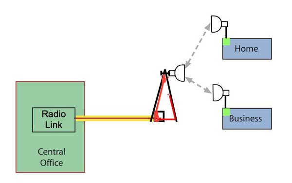
Line-of-sight WiFi or other wireless networks can be used
where cables are too expensive to install.
WiFi which has become available inside
many businesses and even outdoors in areas served by
municipal networks and satellite wireless, is used in many
rural areas where distances are so large that cabling or
WiFi is unfeasible. Options are primarily 5G since other
proposed systems like WiMAX and Super WiFi, land-based
wireless with longer ranges and higher bandwidth
capability than most cellular systems have not been
accepted.
Small cell antennas with more localized
coverage like the original small cell Light Cube Radio
introduced by Alcatel-Lucent several years ago can be
placed anywhere and connected with fiber and power. Small
cells with 5G service are claimed to be capable of
providing more bandwidth to users more efficiently. That
assumes the 5G antenna is working at millimeter wave
frequencies, not current cellular frequencies, but mm wave
radio waves can have a problem penetrating walls, glass,
trees and leaves, clouds, fog, snow, rain, etc.
Their claim is that 5G offers enough bandwidth to
compete with fiber optics, but 5G has a problem getting
inside buildings. A 5G home Internet connection places
an antenna outside the building, comes into the building
on wires and has a module inside the building to provide
wired and wireless connectivity. As we write this,
service providers have just started promoting 5G
Internet, so it's performance is unproven.
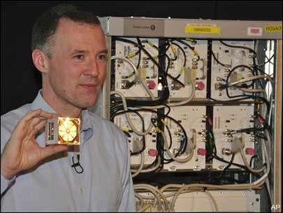
Small cells like the one below are
being installed in many cities around the world. They can
offer better cellular service and perhaps with the
introduction of 5G offer broadband type Internet speeds.

All these wireless systems depend on
the same fiber optic communications backbones that
everyone else does. As they grow, higher bandwidth demands
means more traffic to local antennas which makes fiber
more attractive. Most cellular users are converting older
antenna towers connected by copper cables or line-of-sight
wireless over to fiber. Fiber is even being used for
connections up towers to wireless antennas as it is
smaller and lighter than the coax cables previously used.
Read more on how
wireless depends on fiber here.
Wireless antennas require lots of
fiber to carry the data to the antenna, of course, but
also require power for the electronics and service calls
for upgrades, something a PON does not require.
The biggest drawback to wireless Internet has
been the cost of cellular service. Customers who want to
download HDTV to watch at home will find generally
wireless connections prohibitively expensive, but 5G may
change that.
FTTH
Active Star Network
The simplest way to connect homes with fiber
is to have a fiber link connecting every home to the phone
company switches, either in the nearest central office
(CO) or to a local active switch.
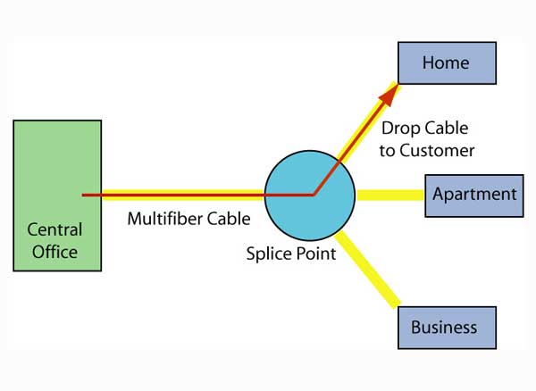
The
drawing above shows a home run connection from the home
directly to the CO, while below, the home is connected to
a local switch, like FTTC upgraded to fiber to the home.
A home run active star network has one fiber dedicated to
each home (or premises in the case of businesses,
apartments or condos.) This architecture offers the
maximum amount of bandwidth and flexibility, but at a
higher cost, both in electronics on each end (compared to
a PON architecture, described below) and the dedicated
fiber(s) required for each home.
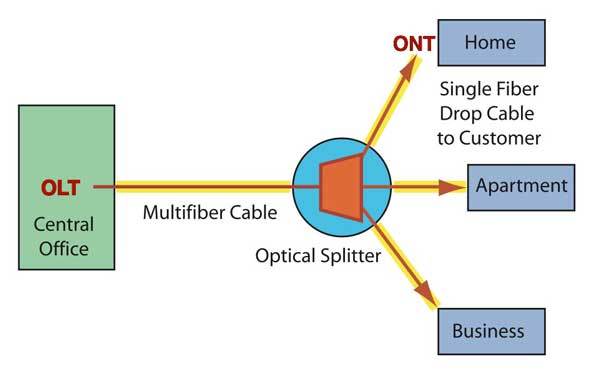
FTTH
PON: Passive Optical Network
A PON system allows sharing expensive components
for FTTH. A passive splitter that takes one input and
splits it to broadcast to many users cuts the cost of the
links substantially by sharing, for example, one expensive
laser with up to 32 or more users. PON splitters are
bi-directional, that is signals can be sent downstream
from the central office, broadcast to all users, and
signals from the users can be sent upstream and combined
into one fiber to communicate with the central office.
Because of all the splitters and short
links, plus since some systems are designed for AM video
like CATV systems, non-reflective connectors (like the
SC-APC angle-polished connector) are generally used.
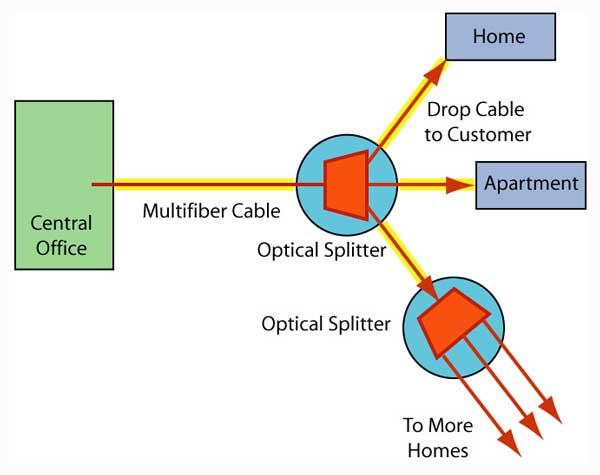
The splitter can be one unit in a single location as shown
above or several splitters cascaded as shown below.
Cascaded splitters can be used to reduce the amount of
fiber needed in a network by placing splitters nearer the
user. The split ratio is the split of each coupler
multiplied together, so a 4-way splitter folllowed by a
8-way splitter would be a 32-way split. Cascading is
usually done when houses being served are clustered in
smaller groups. Splitters are sometimes housed in the
central office and individual fibers run from the office
to each subscriber. This can enhance serviceability of the
network since all the network hardware is in one location
at only a small penalty in overall cost for either dense
urban areas or long rural systems.
Most PON splitters are 1X32 or 2X32 or some smaller
number of splits in a binary sequence (2, 4,8, 16, 32, 64,
128, etc.). Couplers are basically symmetrical, say 32X32,
but PON architecture doesn't need but one fiber connection
on the central office side, or maybe two so one is
available for monitoring, testing and as a spare, so the
other fibers are cut off. Couplers work by splitting the
signal equally into all the fibers on the other side of
the coupler, Splitters
add considerable loss to a FTTH link, limiting the
distance of a FTTH link compared to typical point-to-point
telco link. When designing a fiber optic network, here are
guidelines on loss in PON couplers.
|
Splitter Ratio
|
1:2
|
1:4
|
1:8
|
1:16
|
1:32
|
1:64
|
1:128
|
|
Ideal Loss / Port (dB)
|
3
|
6
|
9
|
12
|
15
|
18
|
21
|
|
Excess Loss (dB, max)
|
1
|
1
|
2
|
3
|
3
|
3
|
3
|
|
Loss (dB)
|
4
|
7
|
11
|
15
|
18
|
21
|
24
|
Each home needs to be connected to the local central
office with singlemode fiber through an
optical splitter. Every home will have a singlemode
fiber link pulled into underground conduit or strung
aerially to the phone company cables running down the
street. Verizon has pioneered installing prefabricated
fiber links that require little field splicing.
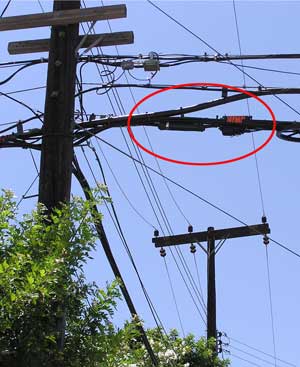
Here is a fiber distribution system that has been
spliced into cables connected to the local central office.
The preterminated drop cable to the home merely connects
to the closure on the pole in the red circle and is
usually lashed to the aerial telephone wire already
connected to the home.
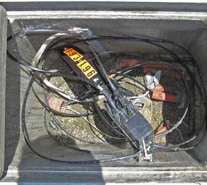
If the cable is underground, it will usually be
pulled through conduit from connection to the distribution
cable or the splitter to the home. Here a preterminated
systems has two home drops connected to the distribution
cable.
The
splitter can be housed in a central office or a pedestal
in the neighborhood near the homes served. Here is a
typical pedestal that has connections to the CO, splitters
and fibers out to each home in a sealed enclosure. The
advantage of PONs is that this pedestal is passive - it
does not require any power as would a switch or node for
fiber to the curb.
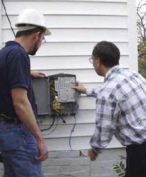
A network interface device containing fiber optic
transmitters and receivers will be installed on the
outside of the house. The incoming cable needs to be
terminated at the house, tested, connected to the
interface and the service tested.
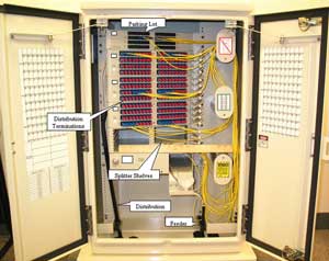
Below is the layout of a typical PON network with the
equipment required at the CO, fiber distribution hub and
the home. This drawing shows the location of the hardware
used in creating a complete PON network. This drawing also
defines the network jargon for cables: a "feeder" cable
extends from the OLT (optical line terminal) in the CO
(central office) to a FDH (fiber distribution hub) where
the PON (passive optical network) splitter is housed. It
then connects to "distribution" cables that go out toward
the subscriber location where "drop" cables will be used
to connect the final link to the ONT (optical network
terminal).
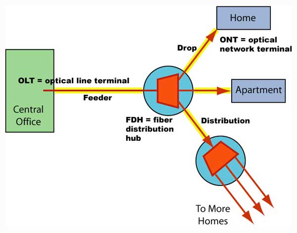
Typical PON network components
Triple
Play Systems
Most service providers' FTTH systems are
"triple play" systems offering voice (telephone), video
(TV) and data (Internet access.) To provide all three
services over one fiber, signals are sent bidirectionally
over a single fiber using two or three separate
wavelengths of light. Three different protocols have been
standardized, BPON, shown below, was the first system used
but now mostly obsolete, used a third wavelength for AM
video, while EPON and GPON use digital IPTV transmission.
Read
more on PON protocols.
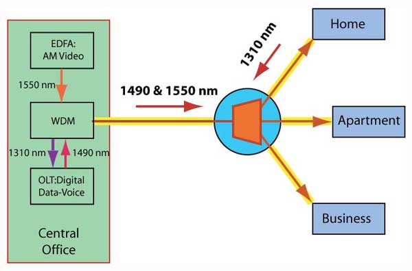
BPON
network with analog TV at 1550nm
Downstream digital signals from the CO
through the splitter to the home are sent at 1490 or 1550
nm. This signal carries both voice and data to the home.
Video on BPON systems used the same technology as CATV, an
analog modulated signal, broadcast separately using a 1550
nm laser which might require a fiber amplifier to provide
enough signal power to overcome the loss of the optical
splitter. GPON and EPON use digital IP TV for video.
Upstream digital signals for voice and data are sent back
to the CO from the home using an inexpensive 1310 nm
laser. WDM couplers separate the signals at both the home
and the CO.
Powering
FTTH
Traditionally, telephone services, at
least what are called "POTS" or plain old telephone
service, have been self-powered from the central office.
POTS phones were on a current loop powered from batteries
or some other type of uninterruptible power in the CO.
When a subscriber had an electrical power outage, they
expected to be able to still use their phone, to call the
electrical utility to report the outage, of course!
Obviously, FTTH is not going to operate the same way.
Fiber does not easily deliver electrical power, although
systems have been developed to power sensors over light in
the fiber, it is inefficient and expensive. Many FTTH
systems provide a battery backup at the customer premises
powered from the customer electrical system to keep the
system operational during power outages. Some systems use
the old copper wires replaced by the fiber to deliver
power to keep the backup charged, so that the FTTH system
provider pays for the power needed by the system. And some
systems, recognizing that most people have a mobile phone,
do not address the issue of backup power at all.
Urban/Suburban/Rural
Geography plays a big part in the
design of a FTTH network, mainly in how it determines
subscriber density. Dense population areas require less
cable and generally higher fiber splitters, suburban areas
with lower density often use cascaded splitters to serve
few subscribers per splitters and rural areas often
require long cable runs and decisions on whether to use
fiber or wireless to connect the subscriber. Rural
networks have several different options including taps for
splitters and remote OLTs. We will discuss this in more
detail in the FTTH
Design page.
- Technical
Information on FTTX From The FOA
Online Guide:
- FTTH
Introduction
- FTTH
Architectures,
- FTTH
in MDUs (Multiple Dwelling Units)
- FTTH
PON Standards, Specifications and Protocols
- FTTH
Design
- FTTH
Installation
- FTTH
Customer Premises Installation
FTTH
Network Testing
FTTH
Case Studies: Do-It-Yourself FTTH
FTTH
Project Management
Migration from GPON to 10GPON
- The
Fiber Optic Association Fiber To The Home Handbook:
For Planners, Managers, Designers, Installers And
Operators Of FTTH - Fiber To The Home - Networks
The
Fiber Optic Association Fiber To The Home
Handbook Available
in paperback or as an eBook on the Amazon
Kindle Available
direct from Amazon.com,
local booksellers and other distributors.
- Training
& Certification
Fiber
U Online FTTx Self Study Program (free)
- FOA
Certification Overview
FOA
FTTx Certification Requirements
FOA-Approved
Training Programs
Table of Contents: The
FOA Reference Guide To Fiber Optics
|
