
| Fiber
Optic Jargon Jump To: Fiber The key to understanding any technology is understanding the language of the technology – the jargon. We’ve started this book with an overview of fiber jargon to introduce you to the language of fiber optics and help you understand what you will be reading in the book. While we try to use the most common terminology, some particular applications for optical fiber have their own specialized terms, and when possible, we will try to include those terms also. We suggest you read this section first to help your understanding of the rest of the book and refer back to it when you encounter a term that you do not recognize. You can also use the definitions in the Glossary or the FOA Online Reference Guide for more explanations. Throughout this page we'll provide links to FOA lectures - videos on YouTube - and pages in the FOA Guide to learn more. What is fiber optics? Fiber optics is sending signals from one location to another in the form of modulated light guided through hair-thin fibers of glass or plastic. These signals can be analog or digital and voice, data or video information. Fiber can transport more information longer distances in less time than any copper wire or wireless method. 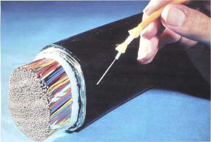 This AT&T PR photo from 1976 shows the relative size of a copper cable that could carry the same amount of information as the single optical fiber. Today a single fiber can carry millions of times more data than that fiber then. Today, fiber optics is the backbone of all communications systems - the Internet, telephone including landlines and wireless, CATV, metropolitan communications, utility smart grids, etc. 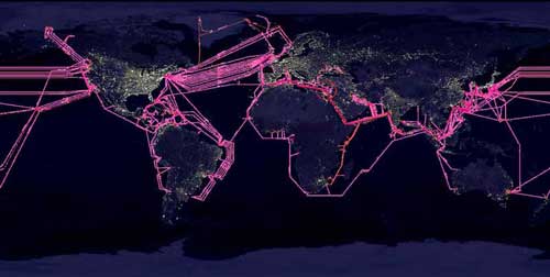
NASA photo of Earth from the ISS, overlaid with the submarine cables (all the hundreds of red lines) that connect the continents. Fiber optic links can transmit data as either analog or digital signals. 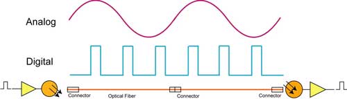 Analog signals are continually varying signals, for example like a vinyl record while digital signals convert the analog signal to digital data and transmit it as pulses representing ones and zeros. 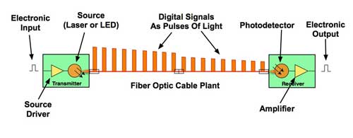 And in operation, it works like this:  A fiber optic datalink uses a transmitter to convert an electrical input signal to a light pulse from an optical source, usually a laser. 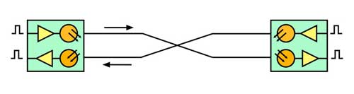 Most fiber optic links transmit in one direction on one fiber and in the opposite direction on another fiber for full duplex operation. 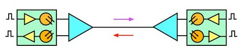 Some links use one fiber to transmit in both directions at one using different wavelengths of light. Fiber to the home passive optical networks (PONs) use this technique. 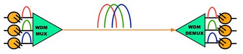 And a single fiber can carry many independent channels at that speed using different wavelengths of light for each channel, called wavelength division multiplexing. Today's networks can transmit data at speeds of over 100 gigabits per second - about 100,000 times faster than the first fiber optic links forty years ago. How "Fast" Is Fiber? We've probably all heard the comment that fiber optics sends signals at the speed of light. But have you ever thought about what that speed really is? The speed of light most people think about is C = speed of light in a vacuum = 300,000 km/s = 186,000 miles/sec. But in glass, the speed is reduced by about 1/3 caused by the material in the glass. The light is slowed down and the amount is defined as the index of refraction of the glass. V= speed of light in a fiber = c/index of refraction of fiber (~1.46) = 205,000 km/s or 127,000 miles/sec. So in glass, the "speed of light" is about 2/3 C, the speed of light in a vacuum. And the difference in speed in different materials is what makes fiber work - causing "total internal refraction" described below. Bottom Line: Fiber is "fast" because of its bandwidth capability Light travels in fiber at the speed of light But the speed of light in glass is only 2/3 as fast as the speed of light in air or a vacuum FOA Lecture 1: Fiber Optics & Communications FOA Lecture 31, Wavelength Division Multiplexing For more on applications of fiber optics, go here. To understand fiber optics, first you need to know the language - the "jargon" - here's a list of terms you should know: The Metric System
Fiber Optical Fiber: Thin strands of highly transparent glass or plastic that guide light. 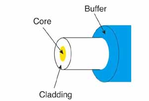 Core: The center of the fiber where the light is transmitted. Cladding: The outside optical layer of the fiber that traps the light in the core and guides it along - even through curves using "total internal reflection," a physical phenomenon caused by the different types of glass in the core and the cladding.  The core of the fiber is of a type of glass that has a slightly higher index of refraction than the cladding, causing the light to bend when it goes from the core to the cladding. Depending on the relative indices of refraction, at some angle the light will be reflected back into the core - what we call total internal reflection. This is the process that captures light in the core and keeps transmitting it with low loss over long distances. Buffer coating or primary buffer coating: A hard plastic coating on the outside of the fiber that protects the glass from moisture or physical damage. The buffer is what one strips off the fiber for termination or splicing. Mode: A single "electromagnetic field pattern" (think of a ray of light) that travels in fiber. Types of Optical Fiber: Fiber types are multimode step index, multimode graded index and singlemode, types determined by the size of the core and the construction of the glass in the core - the index profile shown below. 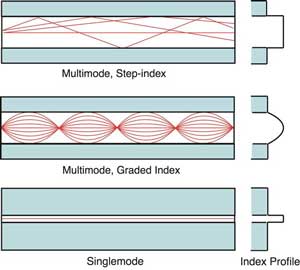 Multimode fiber: has a larger core (almost always 50 or 62.5 microns - a micron is one one millionth of a meter) and is used with laser or LED sources at wavelengths of 850 and 1300 nm for short distance, lower speed data networks like LANs. Step index fiber has a simple glass core and light travels in straight modes causing dispersion.  Graded index fiber has a complex core that compensates for dispersion for higher bandwidth.  Singlemode fiber: has a much smaller core, only about 8-9 microns, so it only transmits one mode. Singlemode is used for telephony (long distance, metropolitan and fiber to the home) and CATV with laser sources at 1310 to 1550 nm. It can go very long distances at very high speeds.  Fiber ID: Fibers are identified by their core and cladding diameters expressed in microns (one millionth of a meter), e.g. 50/125 micron multimode fiber. Most multimode and singlemode fibers have an outside diameter of 125 microns - about 0.005 - 5 thousandths of an inch - just slightly larger than a human hair. International standards also have names for fibers that call out detailed specifications that include bandwidth capability or other special characteristics. Multimode fiber standards. Singlemode fiber standards. 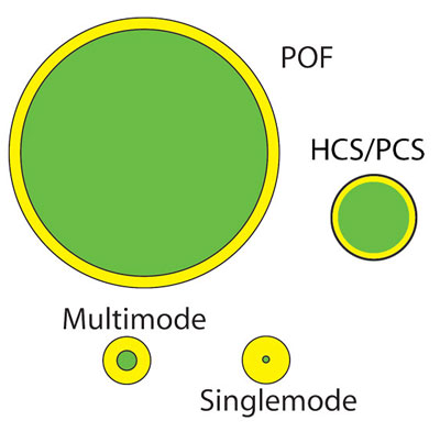 These are the three most common fibers: 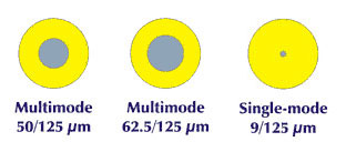
Plastic optical fiber (POF): is a large core (usually 1mm) multimode fiber that can be used for short, low speed networks. POF is used in consumer HiFi and as part of a standard for car communication systems called MOST More on POF. HCS/PCS are plastic-clad silica (glass) fibers used for special applications. Bend insensitive (BI) fiber: fiber that has been designed and manufactured to reduce losses caused by bends in the fiber. It is used in cables that are more likely to incur stress losses such as premises cables and microcables with densely-packed fibers. See this page on BI fibers. FOA Lecture 3: Optical Fiber For more on optical fiber, go here. Fiber Optic Cable Cable: Cable provides protection to the fiber from stress during installation and from the environment once it is installed. Cables may contain from only one to hundreds of fibers inside. Cables come in three varieties: tight buffer with a thick plastic coating on the fibers for protection, used mainly indoors, loose-tube, where fibers with only a primary buffer coating are inside plastic tubes, and ribbon, where fibers are made into ribbons to allow small cables with the largest numbers of fibers. Cable construction: here are the parts of a cable you will see in the photos below: Jacket: The tough outer covering on the cable. Cables installed inside buildings must meet fire codes by using special jacketing materials. Strength members: Aramid fibers (Kevlar is the duPont trade name) used to pull the cable. The term is also used for the fiberglass rod in some cables used to stiffen it to prevent kinking. Armor: Prevents crushing and discourages rodents from damaging cable by chewing through it. Some cable called armored also includes layers of strengthening wires for use in extreme environments such as encountered by submarine cables. Sheath: A term used for the combination of the jacket, armor and any other elements used to protect the fibers in a cable. Cable types - outdoor cables: Outdoor cables are strong and water blocked to withstand outdoor environments. They also have strength members to withstand tension caused by pulling in conduit or aerial spans. Fibers are only coated to a 250 micron diameter to get more fibers in a cable. The fibers are either in tubes or ribbons. 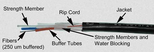 Loose tube cable is the most common OSP cable. It can be installed underground pulled into ducts or aerial when lashed to a messenger cable. 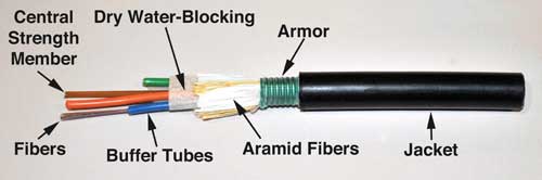 Armored cable is used when buried directly underground without conduit or ducts. The armor resists crushing loads and rodent attacks. 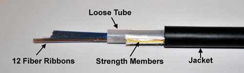 Ribbon cable has bonded ribbons of 12 or 24 fibers stacked directly on top of each other. This is usually the cable that has the most fibers for the smallest cable diameter and is often used when many fibers are needed. The competitor to ribbon cable for smallest size is microcables. These densely packed cables are about 1/2 the size of regular loose tube cables. they are generally installed by blowing them into microducts.  Microcables use fibers with smaller primary buffer coatings around 200 microns and bend-insensitive fibers to reduce cable sizes to about half the size of regular loose tube cables. These cables are generally intended for blowing into microducts. Premises (indoor cables): these cables typically use fibers which have a large soft plastic tight buffer 900 microns diameter extruded over the fiber to make it more rugged and easier to terminate. 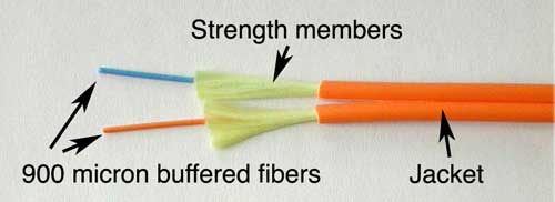 Simplex and zipcord are single tight buffered fibers surrounded by strength members and covered by a plastic jacket. As premises cables the jacket is rated for flame retardance. 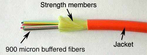 Distribution cable is a bundle of tight buffered fibers surrounded by strength members and a jacket. It's one of the most popular designs for premises installation. 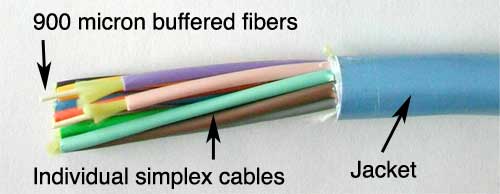 Breakout cable is an extra-rugged cable made from bundles of simplex cables inside a jacket. It's used often when one needs cables broken out and terminated at many separate points. FOA Lecture 4: Fiber Optic Cables (Go here for more on cables) Cable Plant Installations "Fiber optic cable plant" is a term used all the time in fiber optics to cover the installed fiber optics that transmits communications signals. It's permanently installed between the two points which you require communications between. It's what you connect your communications electronics to with patchcords on each end. The cable plant includes all the fiber optic cable, splices, termination and hardware between those two points. 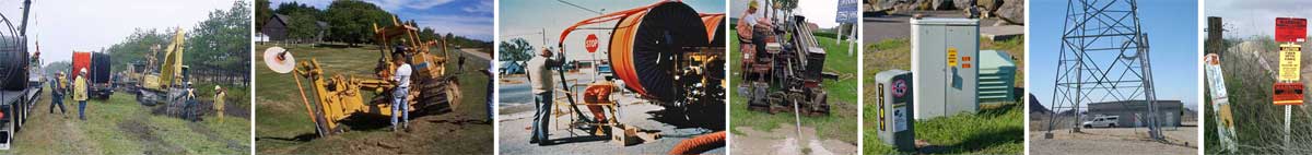 Outside plant (OSP) installations fall into four general categories, depending on the placement of the cable. Each requires cable types chosen for the installation and specialized equipment for placement. Underground: Cables placed underground in conduit buried in trenches, often inside innerduct pulled in the conduit. Ducts may also be installed by directional boring. Cables can also be blown into duct lines installed by trenching or plowing. Direct Buried: Cable placed underground without conduit, placed in trenches or plowed into the ground. Aerial: Cable placed above ground on utility poles. Submarine: Cables placed underwater, including those in shallow water such as lakes or rivers as well as those used for ocean crossings. 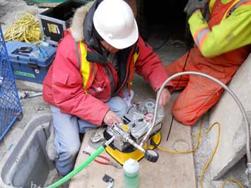 Blown cable is a way of installing microcables in underground ducts by floating the cable on a fast moving stream of air and pushing the cable into the duct, even up to several km. Go here for information on OSP construction techniques. Premises cable installations are indoors, either terminating OSP cables and connecting to communications equipment or in-building LANs (local area networks of computers). 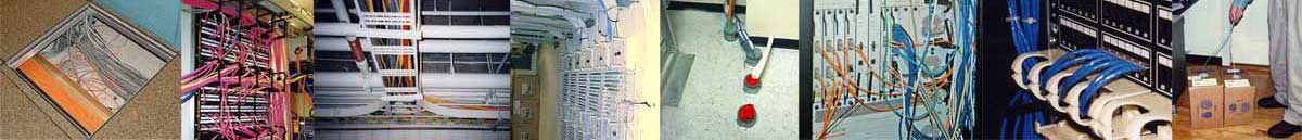 FOA Lecture 8: Fiber Optic Installation For more on fiber optic installations, go here. Splicing and Termination 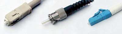 Connector: A non-permanent device for connecting two fibers in a non-permanent joint or connect fibers to equipment. Connectors are expected to be disconnected occasionally for testing or rerouting. (From left: SC, ST and LC are the most popular connectors. Parts for an ST connector are shown below.) 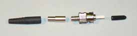 Ferrule: A tube in the connector which holds a fiber for alignment when mated to another connector Splice: a permanent joint between two fibers  Mechanical Splice: A splice where the fibers are aligned created by mechanical means Fusion Splice: A splice created by welding or fusing two fibers together Fusion Splicer: An instrument that splices fibers by fusing or welding them, typically by electrical arc. Hardware: Terminations and Splices require hardware for protection and management: patch panels, splice closures (shown below), etc. 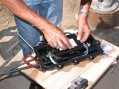 FOA Lecture 5: Splices and Connectors (Here's more on splicing and terminations) Fiber Performance Specifications Terms you use when you want to specify fibers or make measurements of fiber optic components or cable plants:  Attenuation: The reduction in optical power as it passes along a fiber, usually expressed in decibels (dB). For fibers, we talk about attenuation coefficient or attenuation per unit length, in dB/km. See optical loss  Scattering: The change of direction of light after striking small particles that causes the majority of loss in optical fibers and is used to make measurements by an OTDR. The other cause of loss in fiber is absorption in particular wavelengths caused by residual water in the fiber.  Dispersion: Pulse spreading caused by modes in multimode fiber (modal dispersion), the difference in speed of light of different wavelengths (CD or chromatic dispersion in multimode or singlemode fiber ) or polarization (PMD or polarization mode dispersion in singlemode) that limits the bandwidth of the optical fiber. Dispersion causes signals to merge and become difficult for a receiver to distinguish. 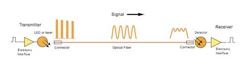 Bandwidth: The range of signal frequencies or bit rate within which a fiber optic component, link or network will operate. 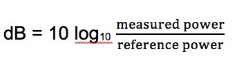 Decibels (dB): A unit of measurement of optical power which indicates relative power. A -10 dB means a reduction in power by 10 times, -20 dB means another 10 times or 100 times overall, -30 means another 10 times or 1000 times overall and so on. dB: Optical power referenced an arbitrary zero level, used to measure loss 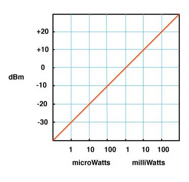 dBm: Optical power referenced to 1 milliwatt, used to measure optical power from transmitters or at receivers. See optical power. Optical Loss: The amount of optical power lost as light is transmitted through fiber, splices, couplers, etc, expressed in "dB." Optical Power: is measured in "dBm", or decibels referenced to one miliwatt of power. while loss is a relative reading, optical power is an absolute measurement, referenced to standards. You measure absolute power to test transmitters or receivers and relative power to test loss. Wavelength: A term for the color of light, usually expressed in nanometers (nm) or microns (m). Fiber is mostly used in the infrared region where the light is invisible to the human eye. Most fiber specifications (attenuation, dispersion) are dependent on wavelength. 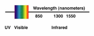 FOA Lecture 12: Fiber Optic Testing Overview FOA Lecture 15: Five Ways To Test Fiber Optic Cable Plants Go here for more information on testing. Tools and Equipment Terms that describe the tools needed for installation and termination: 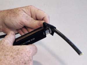 Jacket Slitter or Stripper: A cutter for removing the heavy outside jacket of cables 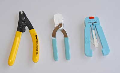
Fiber Stripper: A precise stripper used to remove the buffer coating of the fiber itself for termination. There at three types in common use, called by their trade names: "Miller Stripper", "No-Nik" and "Micro Strip." 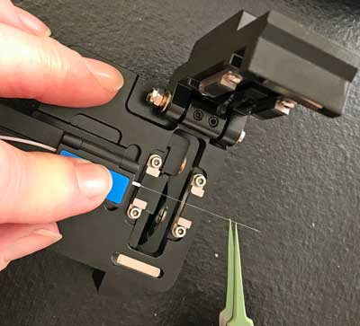 Cleaver: A tool that precisely "breaks" the fiber to produce a flat end for polishing or splicing. 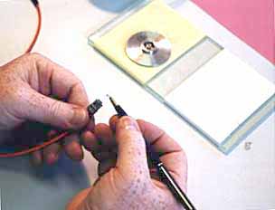 Scribe: A hard, sharp tool that scratches the fiber to allow cleaving manually. 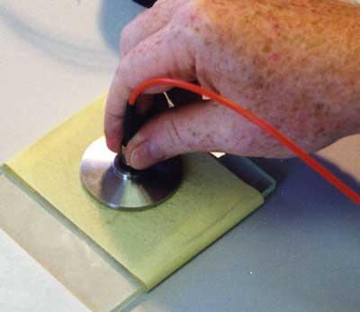 Polishing Puck: for connectors that require polishing, the puck holds the connector in proper alignment to the polishing film. Polishing Film: Fine grit film used to polish the end of the connector ferrule. 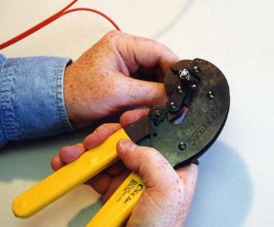 Crimper: A tool that crimps the connector to the aramid fibers in the cable to add mechanical strength. 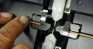 Fusion Splicer: An instrument that welds two fibers together into a permanent joint. FOA Lecture 6: Fiber Optic Splices FOA Lecture 7: Fiber Optic Connectors Here is more information on splicing and termination. Testing Terms that describe fiber optic test equipment:  Optical Power Meter: An instrument that measures optical power from the end of a fiber Test Source: an instrument that uses a laser or LED to send an optical signal into fiber for testing loss of the fiber 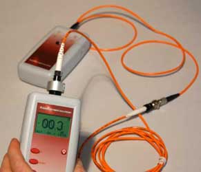 Optical Loss Test Set (OLTS): A measurement instrument that includes both a meter and source used for measuring insertion loss of installed cable plants or individual cables. Also called light source and power meter (LSPM.) 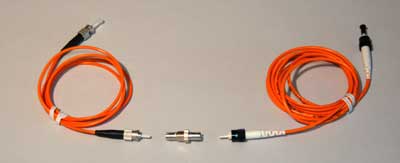 Reference Test Cables: short, single fiber cables with connectors on both ends, used to test unknown cables. Mating Adapter: also called splice bushing or couplers, allow two cables with connectors to mate. 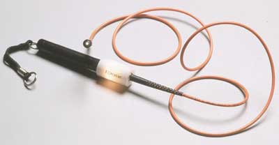 Fiber Tracer: An visible light source (LED or flashlight) that allows visual checking of continuity and tracing for correct connections such as duplex connector polarity 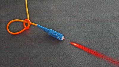 Visual Fault Locator: A high-powered visible laser light source that allows continuity testing, fiber tracing and location of faults near the end of the cable. 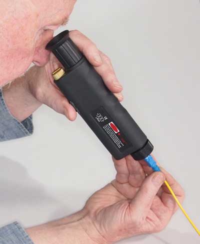
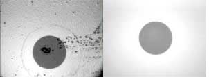 Inspection Microscope: used to inspect the end surface of a connector for faults such as scratches, polish or dirt. 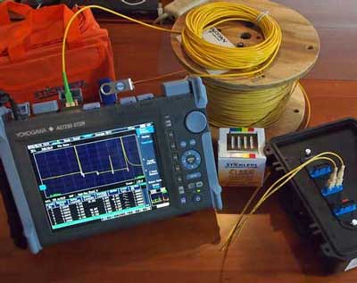 Optical Time Domain Reflectometer (OTDR): An instrument that uses backscattered light to take a snapshot of an optical fiber which can be used to measure fiber length, splice loss, fiber attenuation and for fault location in optical fiber from only one end of the cable. Specialized Testers for Fiber Characterization: Long distance networks may need testing for chromatic dispersion (CD) and polarization mode dispersion (PMD). Systems using wavelength-division multiplexing may need testing for spectral attenuation. Each performance factor has a specialized tester for that specification. FOA Lecture 12: Fiber Optic Testing Overview FOA Lecture 15: Five Ways To Test Fiber Optic Cable Plants For more on testing, go here. More For a complete glossary/dictionary of fiber optic terms, go here.For a complete listing of FOA YouTube Videos, go here.For the complete Table of Contents of the FOA Guide, go here.Test Your Comprehension.Table of Contents: The FOA Reference Guide To Fiber Optics |
|
|