
While the low loss of optical fiber allows signals to travel hundreds of kilometers, extremely long haul lines and submarine cables require regenerators or repeaters to amplify the signal periodically. In the beginning, repeaters basically consisted of a receiver followed by a transmitter. The incoming signal was converted from a light signal to an electrical signal by a receiver, cleaned up to remove as much noise as possible, then was retransmitted by another laser transmitter.
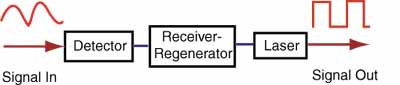
Figure 1. Electronic Repeater
These repeaters added noise to the signal, consumed
much power and were complicated, which means they were a source of
failure. They also had to be made for the specific bit rate of
transmission and upgrading required replacing all the repeaters, a
really difficult task in an undersea cable!
Since the 1960s, researchers knew how to make fiber lasers. Proper
doping of the fiber (introducing small amounts of active elements into
the glass fiber) allowed it to be pumped with external light sources
until stimulated emission occurred. While making fiber amplifiers was
hypothesized early in the stages of fiber optic development, it was not
until 1987 that working models were realized. Major contributors to the
development included Bell Labs and NTT.
The typical fiber amplifier works in the 1550 nm band and consists of a
length of fiber doped with Erbium pumped with a laser at 980. The pump
laser supplies the energy for the amplifier, while the incoming signal
stimulates emission as the pulse passes through the doped fiber.
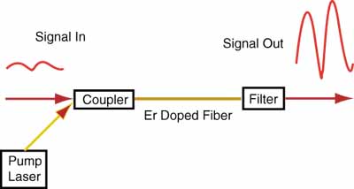
Figure 2. Basic Fiber Amplifier
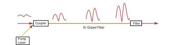
The stimulated emission stimulates more emission, so
there is a rapid, exponential growth of photons in the dopedfiber. Gains
of >40 dB (10,000X) are possible with power outputs >+20 dBm (100
mW).
To date, the most efficient fiber amplifiers have been
Erbium-Doped Fiber Amplifiers (EDFAs) operating in the 1550 nm range.
Since most systems still work at 1310 nm, considerable research has been
done to find materials that would work in this range. Praseodymium-doped
fluoride fiber amplifiers (PDFFAs) using fibers made from zirconium
fluoride or hafnium fluoride have shown some promise, but have not
developed the performance needed for widespread applications.
The basic structure of an EDFA is very simple. The amplifier itself
emits light energy in a signal wavelength (usually about 1540nm) using
energy supplied to it by photons in a pump wavelength (usually 980nm)
when stimulated by incoming photons in the signal - the signal which
needs amplification. Just like in a laser, the emitted photons then
stimulate other emissions, so there is an exponential growth of photons.
Supporting the amplifier is a pump laser, which supplies the amplifier's
energy, a coupler, which combines the pump laser beams and the signal
laser beam and puts them on a single fiber, and an optical filter, which
removes the remaining traces of the pump beam so that it doesn't
interfere with reception of the signal.
Why Erbium?
Erbium has several important properties that make it
an excellent choice for an optical amplifier. Remember that there are
several very specific bands (wavelengths) that fiber optic cables can
carry. Erbium ions (Er3+) have quantum levels that allows them to be
stimulated to emit in the 1540nm band, which is the band that has the
least power loss in most silica-based fiber. That gives them the ability
to amplify signals in a band where high-quality amplifiers are most
needed.
Erbium's quantum levels also allow it to be excited by a signal at
either 800nm or 980nm, both of which silica-based fiber can carry
without great losses, but aren't in the middle of the signal
wavelengths. Those bands are also far enough away from the signal bands
that it is easy to keep the pump beam and the signal beam separated.
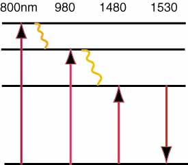
Figure 4. Energy States of Erbium
When erbium is excited by photons at 800nm or 980nm,
it has a non-radiative decay (energy drops without producing light) to a
state where it can stay excited for relatively long periods of time - on
the order of 10ms. This property is extremely important, because the
quantum efficiency of the device is dependent on how long it can stay in
that excited state. If it relaxes too quickly, more photons are needed
to keep it excited, meaning more input power is needed to make the
amplifier work.
Erbium can also be excited by photons at 1480nm, but
this is typically undesirable. When excited at that wavelength, both the
energy pumping process and the stimulated emission by the signal are
happening in the same wavelength and energy band, which can create
interactions that lower the efficiency of the device and increase the
amplifier noise.
Another important property of erbium for use in a
fiber amplifier is that it is fairly soluble in silica, making it easy
to dope into mixtures for making silica-based fiber. For many
applications, reasonable EDFAs can be made by simply dissolving Er2O3 in
a crucible with the SiO2 used to make silica fiber. By using a
co-dopant, such as Al2O3, GeO2-Al2O3, or P2O5, the erbium compound's
solubility in the silica mixture can be greatly increased, and some of
the EDFA's properties can be improved. For example, GeO2-Al2O3 can be
used to almost double the time it takes for excited erbium to relax,
which therefore almost doubles the quantum efficiency of the EDFA.
Alternative Designs
The simple diagram of an EDFA shown in Figure 2 is not the only way
EDFAs can be made. Pumping can be done in a forward direction as shown,
backward from the output end or in both directions. Optical isolators
are commonly used at both ends of the EDFA to prevent pump energy from
escaping back down the fiber or unwanted reflections that may affect
laser stability. Filters, often Bragg gratings (filters fabricated in
fibers), are used to flatten the gain over the broadest wavelength range
for use in WDM systems.
Future Developments
Fiber amplifiers continue to be developed to support Dense Wavelength
Division Multiplexing and to expand to the other wavelength bands
supported by fiber optics. Now that fiber manufacturers have all but
removed the water bands from the spectrum, there is now a range of 1260
to 1610 nm available for use. Fiber amplifiers and diode lasers will
probably be developed within this band to completely fill it with
useable bandwidth.
Our thanks to Chris Cox, Craig Metz and Ron Taylor who researched and created much of the material in this page as a project at Virginia Tech.
(C) 2003-20, The Fiber Optic Association,
Inc.
Return to the FOA Guide Table of Contents or the FOA Home Page